Inst ToolsInst ToolsInst Tools
  • Courses
  • Automation
    • PLC
    • Control System
    • Safety System
    • Communication
    • Fire & Gas System
  • Instrumentation
    • Design
    • Pressure
    • Temperature
    • Flow
    • Level
    • Vibration
    • Analyzer
    • Control Valve
    • Switch
    • Calibration
    • Erection & Commissioning
  • Interview
    • Instrumentation
    • Electrical
    • Electronics
    • Practical
  • Q&A
    • Instrumentation
    • Control System
    • Electrical
    • Electronics
    • Analog Electronics
    • Digital Electronics
    • Power Electronics
    • Microprocessor
Search
  • Books
  • Software
  • Projects
  • Process
  • Tools
  • Basics
  • Formula
  • Power Plant
  • Root Cause Analysis
  • Electrical Basics
  • Animation
  • Standards
  • 4-20 mA Course
  • Siemens PLC Course
Reading: Alarm Annunciator Circuit with Acknowledge
Share
Notification Show More
Font ResizerAa
Inst ToolsInst Tools
Font ResizerAa
  • Courses
  • Design
  • PLC
  • Interview
  • Control System
Search
  • Courses
  • Automation
    • PLC
    • Control System
    • Safety System
    • Communication
    • Fire & Gas System
  • Instrumentation
    • Design
    • Pressure
    • Temperature
    • Flow
    • Level
    • Vibration
    • Analyzer
    • Control Valve
    • Switch
    • Calibration
    • Erection & Commissioning
  • Interview
    • Instrumentation
    • Electrical
    • Electronics
    • Practical
  • Q&A
    • Instrumentation
    • Control System
    • Electrical
    • Electronics
    • Analog Electronics
    • Digital Electronics
    • Power Electronics
    • Microprocessor
Follow US
All rights reserved. Reproduction in whole or in part without written permission is prohibited.
Inst Tools > Blog > Control Systems > Alarm Annunciator Circuit with Acknowledge

Alarm Annunciator Circuit with Acknowledge

Last updated: September 22, 2021 7:27 pm
Editorial Staff
Control Systems
No Comments
Share
2 Min Read
SHARE

Explain how the following annunciator circuit works:

Alarm annunciator circuit with acknowledge

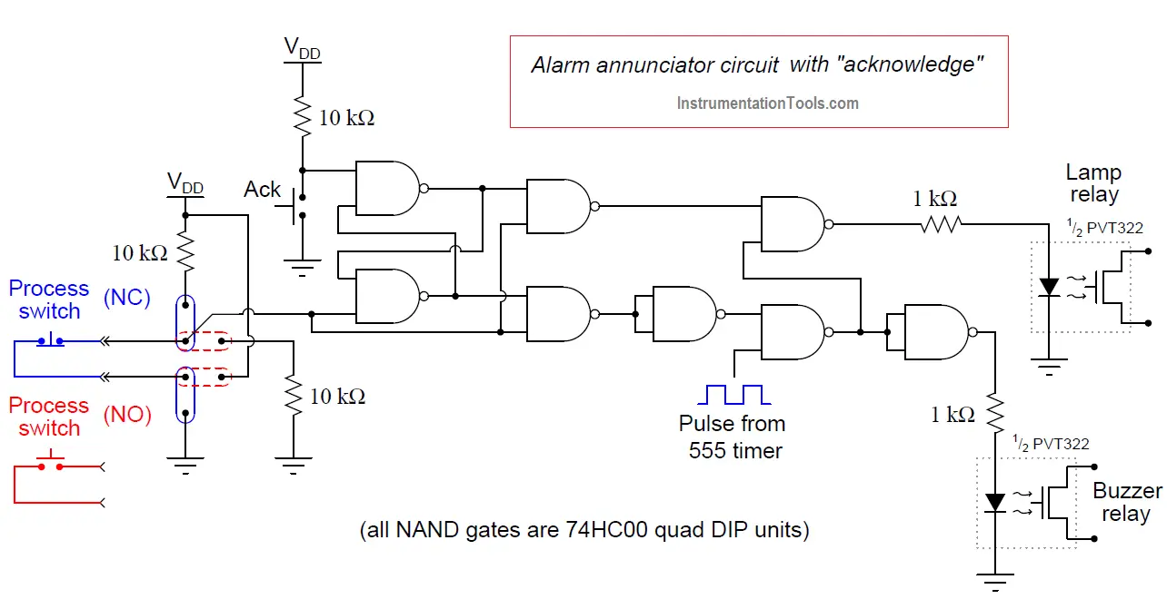
Note the jumper options shown in the diagram: one set of jumper positions configures the alarm for a process switch that alarms when its contacts open, and the other positions configure the alarm for a process switch that alarms when its contacts close.

In either case, the circuit is designed to indicate an alarm status when the line going in to the lower-left NAND gate goes high.

Alarm Annunciator Circuit with Acknowledge

The first two (left-most) NAND gates form an active-low S-R latch circuit. That is, a “low” state on the upper input (from the acknowledge switch) sets the S-R latch so that the upper NAND gate outputs a high signal, and a “low” state on the lower input (process switch returning to a non-alarm condition) “resets” the S-R latch so that the lower NAND gate outputs a high signal.

Thus, the purpose of the S-R latch is to remember the “acknowledged” status of the alarm point. Actuating the “Ack” switch sets the latch and acknowledges the alarm.

Having the process switch return to a normal (non-alarm) status resets the latch and prepares the circuit for full alert (flashing light and pulsing buzzer) for the next alarm state.

Credits: Tony R. Kuphaldt

Read Next:

  • What is Calibration?
  • Instrument Zero and Span Calibration
  • How to do Transmitter Calibration?
  • Instruments Calibration Procedure
  • Questions & Answers on Calibration
  • Alarms and Interlocks
Don't Miss Our Updates
Be the first to get exclusive content straight to your email.
We promise not to spam you. You can unsubscribe at any time.
Invalid email address
You've successfully subscribed !

Continue Reading

Proportional Controller Principle
Free PID Controller Gains Tuning Tool
Instrumentation Earthing
Serial Communication Error Checking Methods and Algorithms
What is Instrument Hook Up Diagram ?
Basics of 4-20mA Current Loop
Share This Article
Facebook Whatsapp Whatsapp LinkedIn Copy Link
Share
Leave a Comment

Leave a Reply Cancel reply

Your email address will not be published. Required fields are marked *

Stay Connected

128.3kFollowersLike
69.1kFollowersFollow
210kSubscribersSubscribe
38kFollowersFollow

Categories

Explore More

Types of Wireless Technologies in Industrial Automation
Open Platform Communication (OPC)
Process Switches and Alarms
PID Controller Loop Tuning Questions and Answers – Part 2
PID Controller Gains Effect on Manipulated Variable
Control Room Design Guidelines
Definitions of Electrical Grounding
Overview of PID Control terms

Keep Learning

Discrete control system block diagram

Process Control Instrumentation

DCS Commissioning Steps

DCS Commissioning Steps

Yokogawa DCS Tutorials - Configuration of Analog Input (Transmitter)

Yokogawa DCS Tutorials – Configuration of Analog Input (Transmitter)

Instrumentation During the Detail Design Phase

Instrumentation Engineer Activities & Documents – Detail Design Phase

2 wire transmitter current loops

2-wire Transmitters Current Loops

Readings Mismatch between Field & Control Room

Readings Mismatch between Field & Control Room ? Why

Control Valve Direction of Control Action

PID Controller Action : Directing Acting & Reverse Acting

annunciator-alarm-simulator

Alarm Simulator for Annunciator Logic

Learn More

Induced Draft Cooling Tower

Cooling Tower

Career Scope in Electronics Engineering

Career Scope in Electronics Engineering

Linear Programming in Excel

How to Do Linear Programming in Excel?

Installation Precautions of Thermocouple and RTD

Installation Precautions of Thermocouple and RTD

Closed-Tank-DP-Type-Level-Measurement-with-wet-leg-and-transmitter-installed-below-tapping-point

Level Measurement with Wet leg and Installed Below Tapping Point

orifice-plate

Orifice Plate Turndown ratio

Fibre Optic Sensors Objective Questions

Fibre Optic Sensors Objective Questions

Multiple Position Calibration of Temperature Chamber (Mapping)

Multiple Position Calibration of Temperature Chamber

Menu

  • About
  • Privacy Policy
  • Copyright

Quick Links

  • Learn PLC
  • Helping Hand
  • Part Time Job

YouTube Subscribe

Follow US
All rights reserved. Reproduction in whole or in part without written permission is prohibited.
Welcome Back!

Sign in to your account

Username or Email Address
Password

Lost your password?