Inst ToolsInst ToolsInst Tools
  • Courses
  • Automation
    • PLC
    • Control System
    • Safety System
    • Communication
    • Fire & Gas System
  • Instrumentation
    • Design
    • Pressure
    • Temperature
    • Flow
    • Level
    • Vibration
    • Analyzer
    • Control Valve
    • Switch
    • Calibration
    • Erection & Commissioning
  • Interview
    • Instrumentation
    • Electrical
    • Electronics
    • Practical
  • Q&A
    • Instrumentation
    • Control System
    • Electrical
    • Electronics
    • Analog Electronics
    • Digital Electronics
    • Power Electronics
    • Microprocessor
Search
  • Books
  • Software
  • Projects
  • Process
  • Tools
  • Basics
  • Formula
  • Power Plant
  • Root Cause Analysis
  • Electrical Basics
  • Animation
  • Standards
  • 4-20 mA Course
  • Siemens PLC Course
Reading: AC Generator Parts
Share
Notification Show More
Font ResizerAa
Inst ToolsInst Tools
Font ResizerAa
  • Courses
  • Design
  • PLC
  • Interview
  • Control System
Search
  • Courses
  • Automation
    • PLC
    • Control System
    • Safety System
    • Communication
    • Fire & Gas System
  • Instrumentation
    • Design
    • Pressure
    • Temperature
    • Flow
    • Level
    • Vibration
    • Analyzer
    • Control Valve
    • Switch
    • Calibration
    • Erection & Commissioning
  • Interview
    • Instrumentation
    • Electrical
    • Electronics
    • Practical
  • Q&A
    • Instrumentation
    • Control System
    • Electrical
    • Electronics
    • Analog Electronics
    • Digital Electronics
    • Power Electronics
    • Microprocessor
Follow US
All rights reserved. Reproduction in whole or in part without written permission is prohibited.
Inst Tools > Blog > Electrical Theory > AC Generator Parts

AC Generator Parts

Last updated: August 2, 2018 9:01 pm
Editorial Staff
Electrical Theory
1 Comment
Share
4 Min Read
SHARE

AC generators are widely used to produce AC voltage. To understand how these generators operate, the function of each component of the generator must first be understood.

Field

The field in an AC generator consists of coils of conductors within the generator that receive a voltage from a source (called excitation) and produce a magnetic flux. The magnetic flux in the field cuts the armature to produce a voltage. This voltage is ultimately the output voltage of the AC generator.

Armature

The armature is the part of an AC generator in which voltage is produced. This component consists of many coils of wire that are large enough to carry the full-load current of the generator.

Prime Mover

The prime mover is the component that is used to drive the AC generator. The prime mover may be any type of rotating machine, such as a diesel engine, a steam turbine, or a motor.

Rotor

The rotor of an AC generator is the rotating component of the generator, as shown in Figure 1. The rotor is driven by the generator’s prime mover, which may be a steam turbine, gas turbine, or diesel engine. Depending on the type of generator, this component may be the armature or the field. The rotor will be the armature if the voltage output is generated there; the rotor will be the field if the field excitation is applied there.

Basic AC Generator

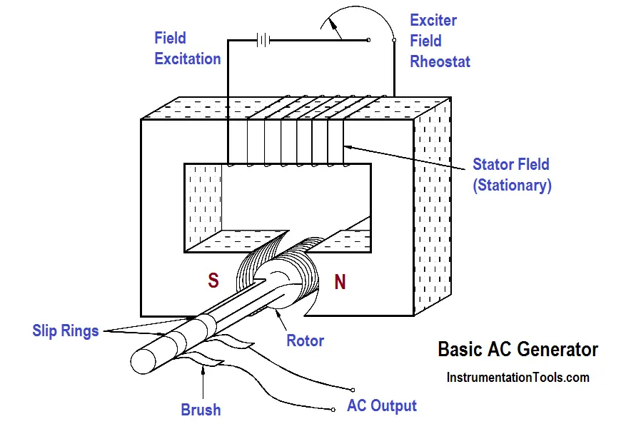
Figure 1 – Basic AC Generator

Stator

The stator of an AC generator is the part that is stationary (refer to Figure 1). Like the rotor, this component may be the armature or the field, depending on the type of generator. The stator will be the armature if the voltage output is generated there; the stator will be the field if the field excitation is applied there.

Slip Rings

Slip rings are electrical connections that are used to transfer power to and from the rotor of an AC generator (refer to Figure 1). The slip ring consists of a circular conducting material that is connected to the rotor windings and insulated from the shaft. Brushes ride on the slip ring as the rotor rotates. The electrical connection to the rotor is made by connections to the brushes.

Slip rings are used in AC generators because the desired output of the generator is a sine wave. In a DC generator, a commutator was used to provide an output whose current always flowed in the positive direction, as shown in Figure 2. This is not necessary for an AC generator. Therefore, an AC generator may use slip rings, which will allow the output current and voltage to oscillate through positive and negative values. This oscillation of voltage and current takes the shape of a sine wave.

Comparison of DC and AC Generator Outputs

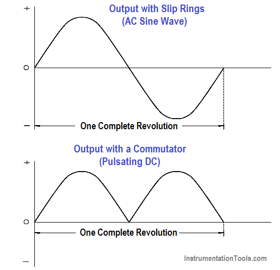
Figure 2 – Comparison of DC and AC Generator Outputs

Don't Miss Our Updates
Be the first to get exclusive content straight to your email.
We promise not to spam you. You can unsubscribe at any time.
Invalid email address
You've successfully subscribed !

Continue Reading

Generator Action in a Motor
Battery Hazards
Series-Wound DC Generators
Magnetism
DC Generator
Battery Terminology
Share This Article
Facebook Whatsapp Whatsapp LinkedIn Copy Link
Share
1 Comment
  • Benson charles says:
    December 14, 2019 at 9:24 pm

    Thanx for,explanation

    Reply

Leave a Reply Cancel reply

Your email address will not be published. Required fields are marked *

Stay Connected

128.3kFollowersLike
69.1kFollowersFollow
208kSubscribersSubscribe
38kFollowersFollow

Categories

Explore More

AC Generator Voltage Regulators
Power Factor Meter Principle
Conductor, Insulator, Resistor and Current Flow
Types of Batteries
Power Factor
Calculate Power in Series RCL Circuit
Transformer Voltage Ratio
Impedance in RLC Circuits

Keep Learning

Inductor Principle

Inductor

Motor Rotating Magnetic Field

AC Motor Theory

Parallel Circuit Parallel Current Calculations

Parallel Circuit Current Calculations

Auto Transformer Schematic

Classification of Transformers

Cutaway View of Circuit Breaker

Low Voltage Air Circuit Breaker Principle

Core-Type Transformer

Transformer Theory of Operation

Calculate Power in Series RC Circuit

Calculate Power in Series RC Circuit

Capacitive Time Constant for Charging Capacitor

Capacitive Time Constant

Learn More

Comparison Instructions in PLC Programming

Comparison Instructions in PLC Programming

Thermocouples Burnout detection

Thermocouples Burnout detection

Is it Possible to Measure liquid-liquid Level Interface using Float

Is it Possible to Measure Liquid-Liquid Level Interface using Float?

Head Mount Temperature Transmitter

What is a Head Mount Temperature Transmitter? – Advantages

Difference between SIS, PLC and BPCS Systems

Difference between SIS, PLC and BPCS Systems

Electrical Machines Questions and Answers

Rotating Electrical Machines Quiz

Machine Learning

Difference Between Machine Learning and Artificial Intelligence?

Analyzer Sample Conditioning

Sodium Analyzer Problems and Troubleshooting Steps

Follow US
All rights reserved. Reproduction in whole or in part without written permission is prohibited.
Welcome Back!

Sign in to your account

Username or Email Address
Password

Lost your password?