This article will discuss PLC programming to monitor water levels in a Dam and provide 5 alarm levels with automatic gates open or close control as per the logic. This PLC system will provide an Alarm Indicator regarding the water level in the Dam. This PLC system will automatically take certain actions based on the detected water level, such as controlling the Water Pump and opening the Dam Gate when the water level exceeds the safety level limit.
Program Objective
- This system has 5 safety level indicators for flood warnings, and the entire system will run automatically.
- When the water level reaches Level-1, the Level-1 Alarm will be Active.
- When the water level rises to Level-2, the Level-2 Alarm will activate and the Drain Valve will open. 2 seconds later, the Water Pump will turn ON to reduce the water flow in the Dam.
- When the water level reaches Level-3, the Level-3 Alarm will activate, and 1 Dam Gate will open.
- When the water level reaches Level-4, the Level-4 Alarm will activate, and 2 Dam Gates will open.
- When the water level reaches Level-5, the Level-5 Alarm will activate, and the 3 Dam Gates will open.
Dam Gate Control with 5 Alarm Levels

Inputs and Outputs Mapping
| S.No. | Comment | Input (I) | Output (Q) | Memory Bits | Timer |
|---|---|---|---|---|---|
| 1 | START | 0.00 | |||
| 2 | STOP | 0.01 | |||
| 3 | SENS_LEVEL1 | 0.02 | |||
| 4 | SENS_LEVEL2 | 0.03 | |||
| 5 | SENS_LEVEL3 | 0.04 | |||
| 6 | SENS_LEVEL4 | 0.05 | |||
| 7 | SENS_LEVEL5 | 0.06 | |||
| 8 | ALARM_LEVEL1 | 100.00 | |||
| 9 | ALARM_LEVEL2 | 100.01 | |||
| 10 | VALVE | 100.02 | |||
| 11 | PUMP | 100.03 | |||
| 12 | ALARM_LEVEL3 | 100.04 | |||
| 13 | GATE_WATER1_OPEN | 100.05 | |||
| 14 | ALARM_LEVEL4 | 100.06 | |||
| 15 | GATE_WATER2_OPEN | 100.07 | |||
| 16 | ALARM_LEVEL5 | 100.08 | |||
| 17 | GATE_WATER3_OPEN | 100.09 | |||
| 18 | TIMER_PUMP | T0000 | |||
| 19 | SYSTEM_ON | W0.00 | |||
| 20 | IR_GATE1 | W0.01 | |||
| 21 | IR_GATE2 | W0.02 |
Explanation of PLC Project
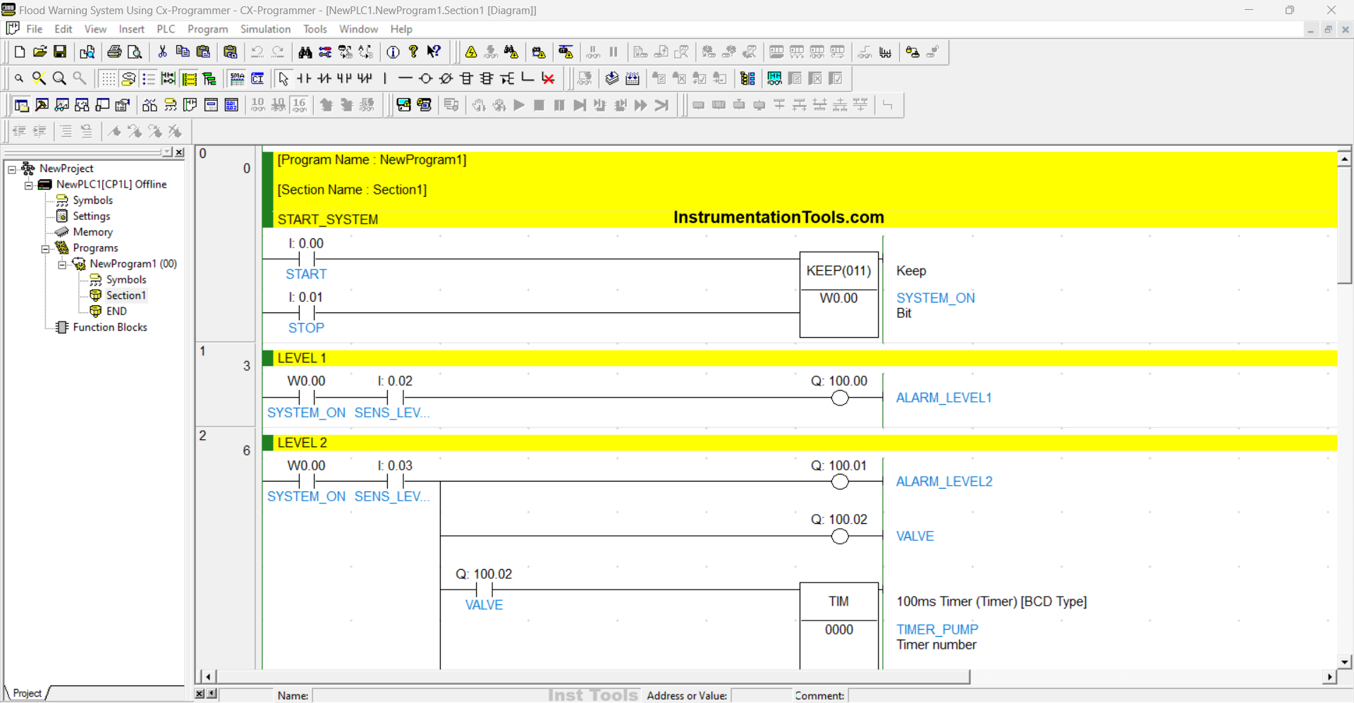
RUNG 0 (START_SYSTEM)
In this Rung, when the START (0.00) button is pressed, the memory bit SYSTEM_ON (W0.00) will be in the HIGH state. Because it uses the KEEP(011) instruction, the memory bit SYSTEM_ON (W0.00) will remain in the HIGH state even though the START (0.00) button has been released.
The memory bit SYSTEM_ON (W0.00) will be in the LOW state if the STOP (0.01) button is pressed.
RUNG 1 (LEVEL 1)
In this Rung, when the NO contact of the memory bit SYSTEM_ON (W0.00) and the sensor SENS_LEVEL1 (0.02) are in the HIGH state, the output ALARM_LEVEL1 (100.00) will be ON.
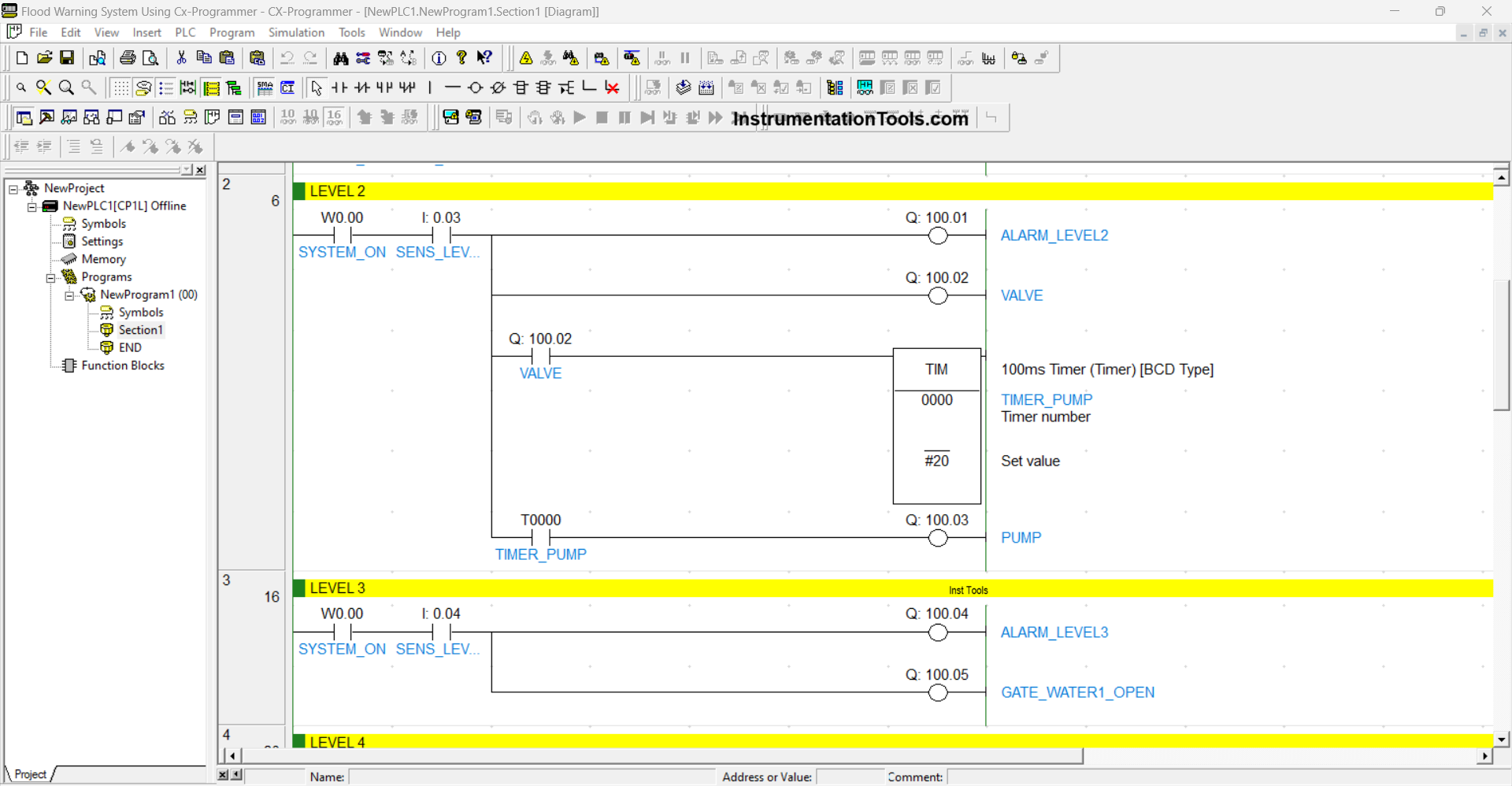
RUNG 2 (LEVEL 2)
In this Rung, when the NO contact from the memory bit SYSTEM_ON (W0.00) and the sensor SENS_LEVEL2 (0.03) are in the HIGH state, the output ALARM_LEVEL2 (100.01) will be ON and the output VALVE (100.02) will be OPEN.
The timer TIMER_PUMP (T0000) will start counting up to 2 seconds when the NO contact of VALVE (100.02) is in the HIGH state. After the timer TIMER_PUMP (T0000) has finished counting, the output PUMP (100.03) will turn ON.
RUNG 3 (LEVEL 3)
In this Rung, when the NO contact of the memory bit SYSTEM_ON (W0.00) and the sensor SENS_LEVEL3 (0.04) are in the HIGH state, the output ALARM_LEVEL3 (100.04) will be ON and the output GATE_WATER1_OPEN (100.05) will be OPEN.
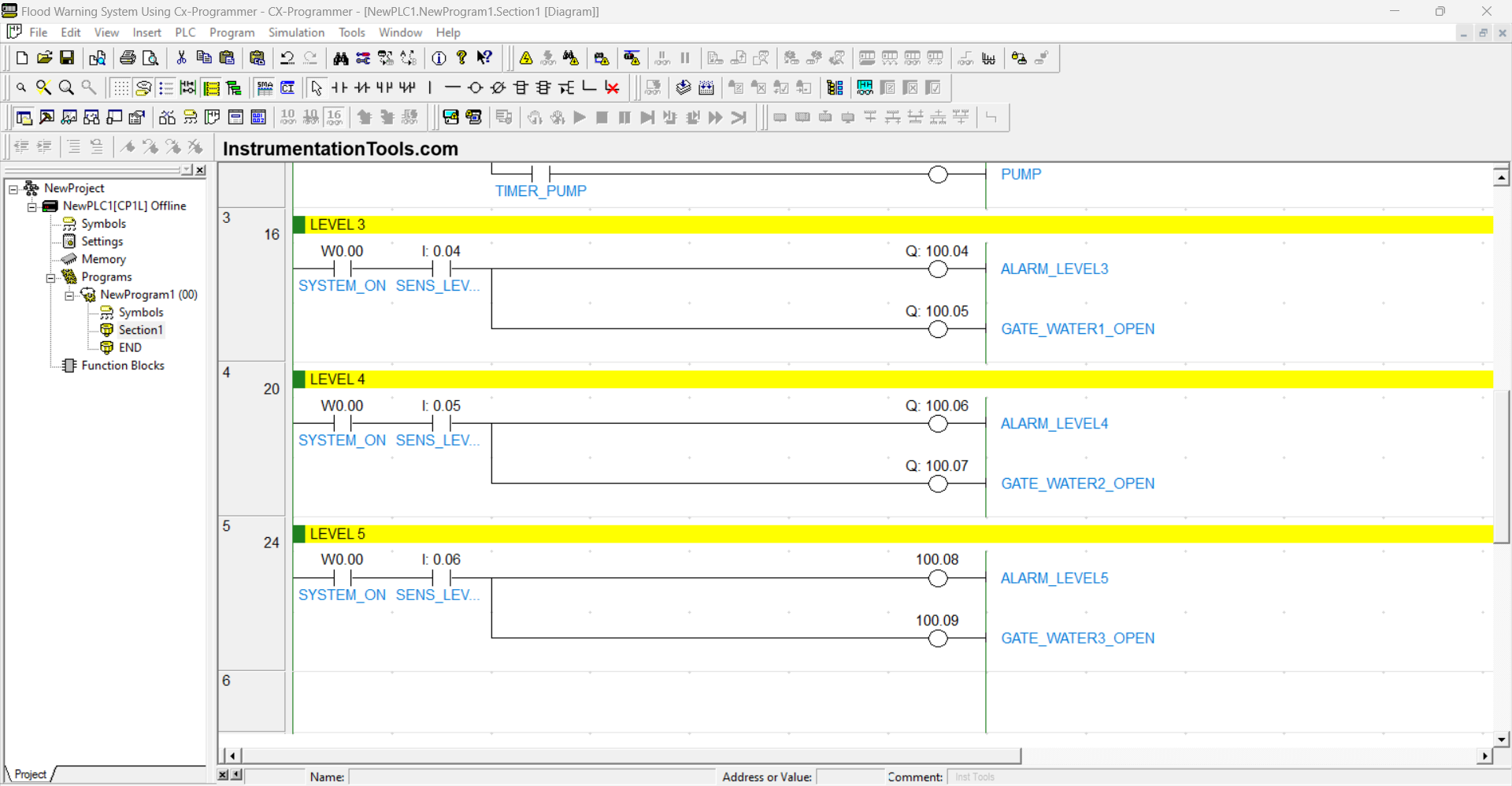
RUNG 4 (LEVEL 4)
In this Rung, when the NO contact of the memory bit SYSTEM_ON (W0.00) and the sensor SENS_LEVEL4 (0.05) are in the HIGH state, the output ALARM_LEVEL4 (100.06) will be ON and the output GATE_WATER2_OPEN (100.07) will be OPEN.
RUNG 5 (LEVEL 5)
In this Rung, when the NO contact of the memory bit SYSTEM_ON (W0.00) and the sensor SENS_LEVEL5 (0.06) are in the HIGH state, the output ALARM_LEVEL5 (100.08) will be ON and the output GATE_WATER3_OPEN (100.09) will be OPEN.
Read Next:
- PLC Program for Paper Cutting by Length and Count
- Siemens TIA Portal: Oven Control with Moving Conveyor
- XG5000 PLC Project: Continuous Liquid Tank Control Logic
- Paint Mixing System Control Program using Siemens PLC
- Latching and Interlocking Pump Control in PLC Programming