This article will discuss how to connect a Mitsubishi PLC to the Modbus Poll software using the Modbus RTU serial communication method. In this system, the PLC will act as the “Slave” while the Modbus Poll software will act as the “Master”, meaning the PLC will receive commands from Modbus Poll. Modbus Poll will be used to send Coil and Holding Register data to the PLC. The Coil data (memory bit) in the PLC is used to activate outputs through NO contacts, while the Holding Register (memory word) stores data, which will then be compared with a reference value to control the output.
Required Devices
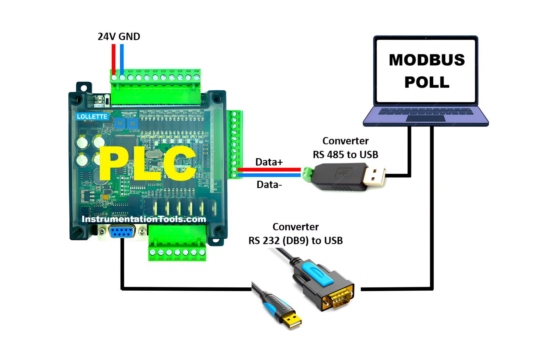
In this system, the PC communicates with the PLC through two channels. Channel 1 uses an RS485 to USB Converter, which connects the PLC to the Modbus Poll software. Channel 2 uses an RS-232 (DB9) to USB Converter to connect the PLC to the GX Works2 software for online monitoring. This setup is necessary because the RS-232 serial port only supports point-to-point communication, meaning it can only connect to one device at a time.
The communication line using the RS485 to USB Converter is configured with the following parameters:
- Baudrate: 9600 bps
- Data Bits: 8
- Parity: 0
- Stop Bit: 1
- Comm. Protocol: MODBUS Slave
- Slave ID: 1
In this configuration, the Slave ID is represented in binary as K1 and is written to the D8121 register using the MOV instruction.
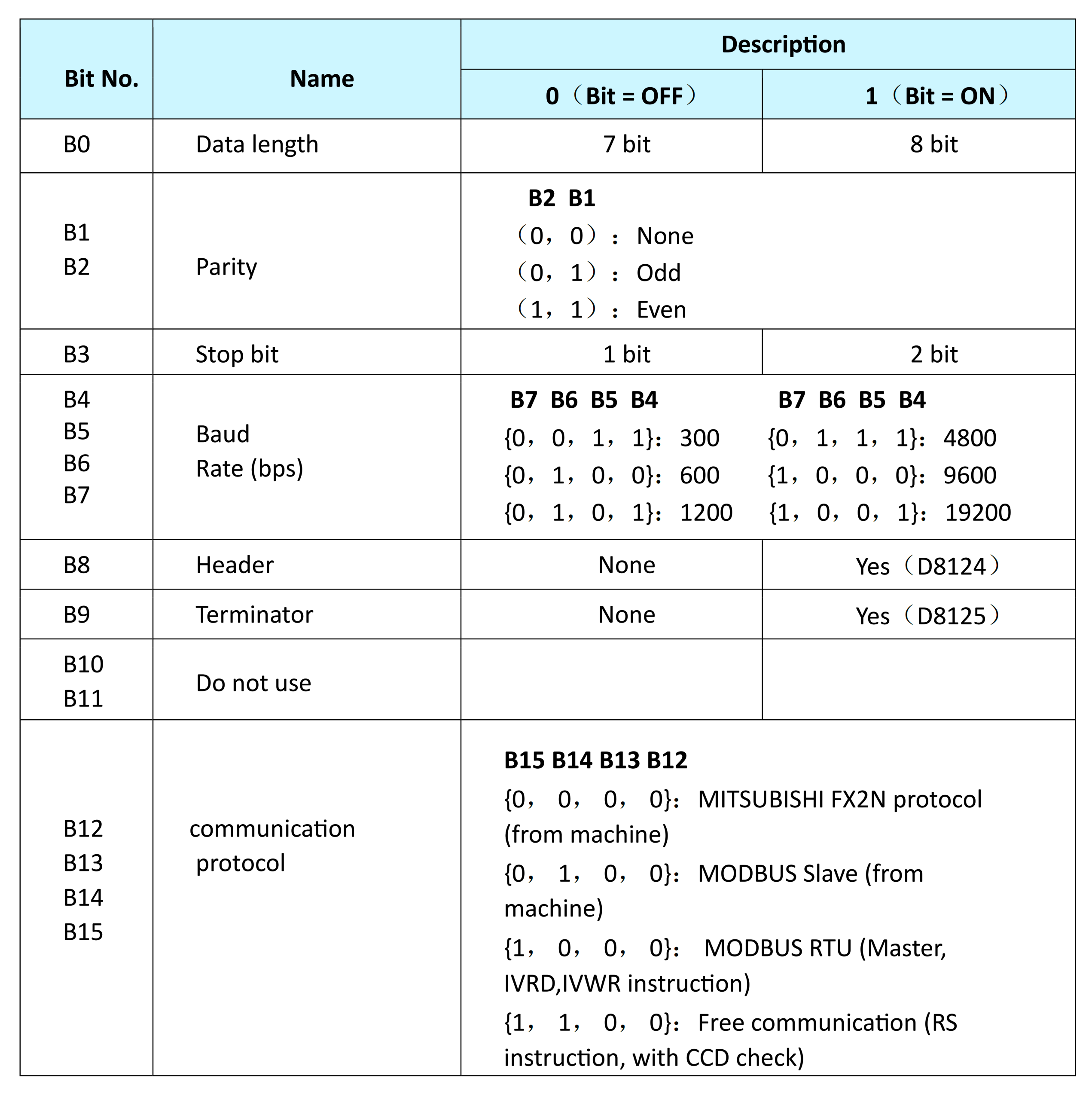
The parameters for Baudrate, Data Bits, Parity, Stop Bit, and Comm. Protocol are combined in hexadecimal format as H4081 and stored in the D8120 register, also using the MOV instruction. The hexadecimal value H4081 corresponds to the binary format 0100 0000 1000 0001, with each bit representing a specific communication setting. These parameter settings refer to the PLC communication configuration format described in the table below.
Communication Settings in D8120
PLC Register Write and Coil Control Using Modbus Poll
Communicate PLC FX3U-14MT with GX-Works2 and Modbus Poll Software
In the video below, we show how to communicate Modbus Master with the Mitsubishi PLC.
Initial Preparation
1. Power Supply Provision
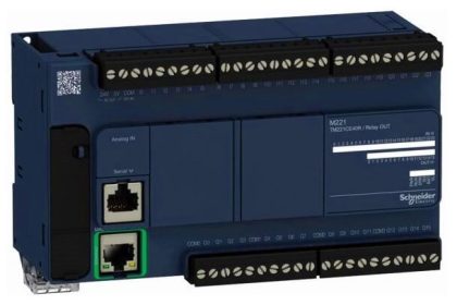
Supply 24 VDC to the FX3U-14MT PLC to power up the device.
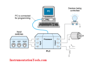
2. Connection Between PLC and Computer
Connect the PLC to the computer using a USB to Serial RS-232 cable and an RS485 to USB converter.
Download the Program and Activate Online Monitoring Mode
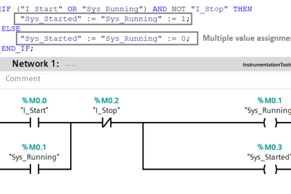
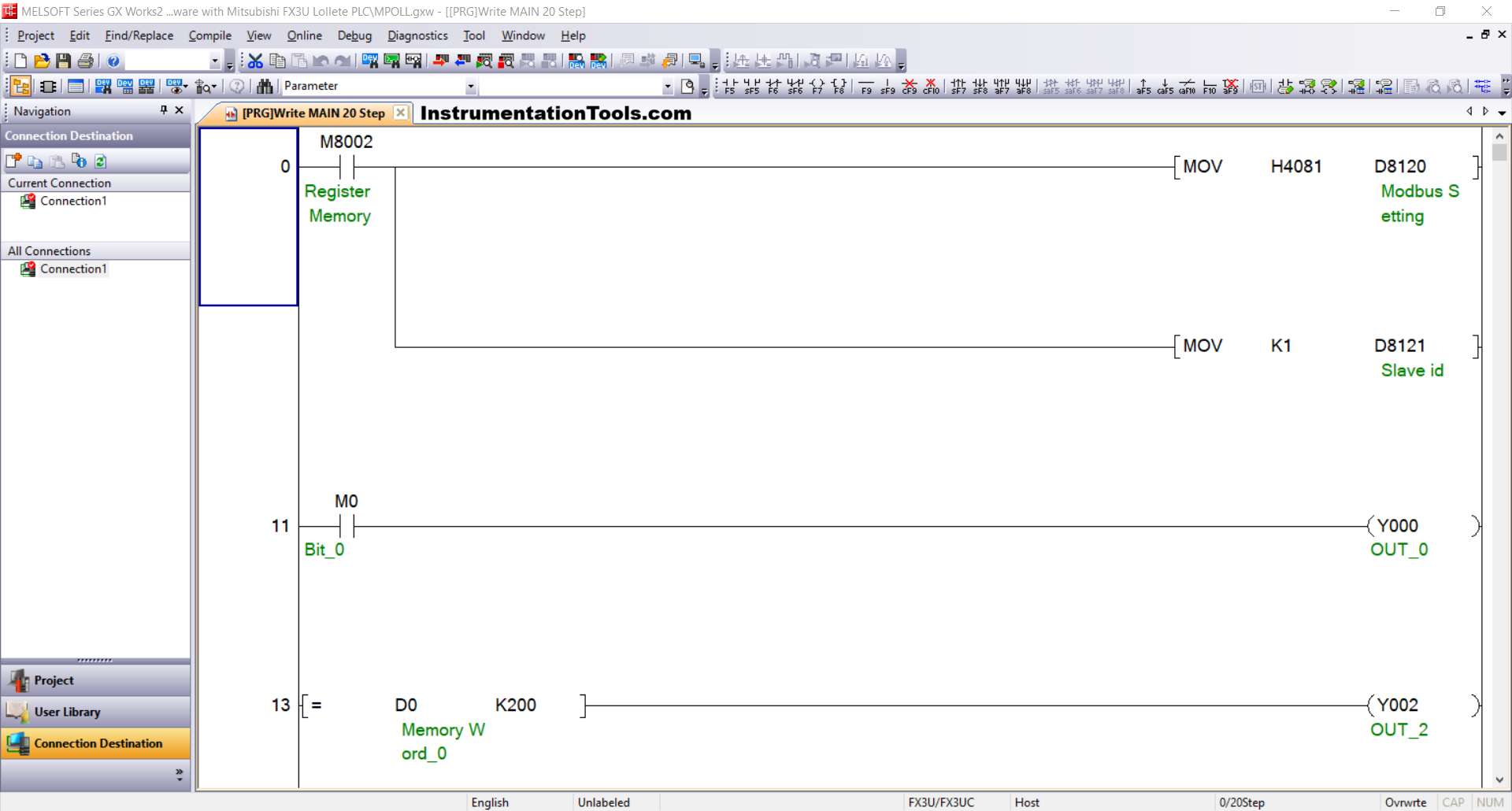
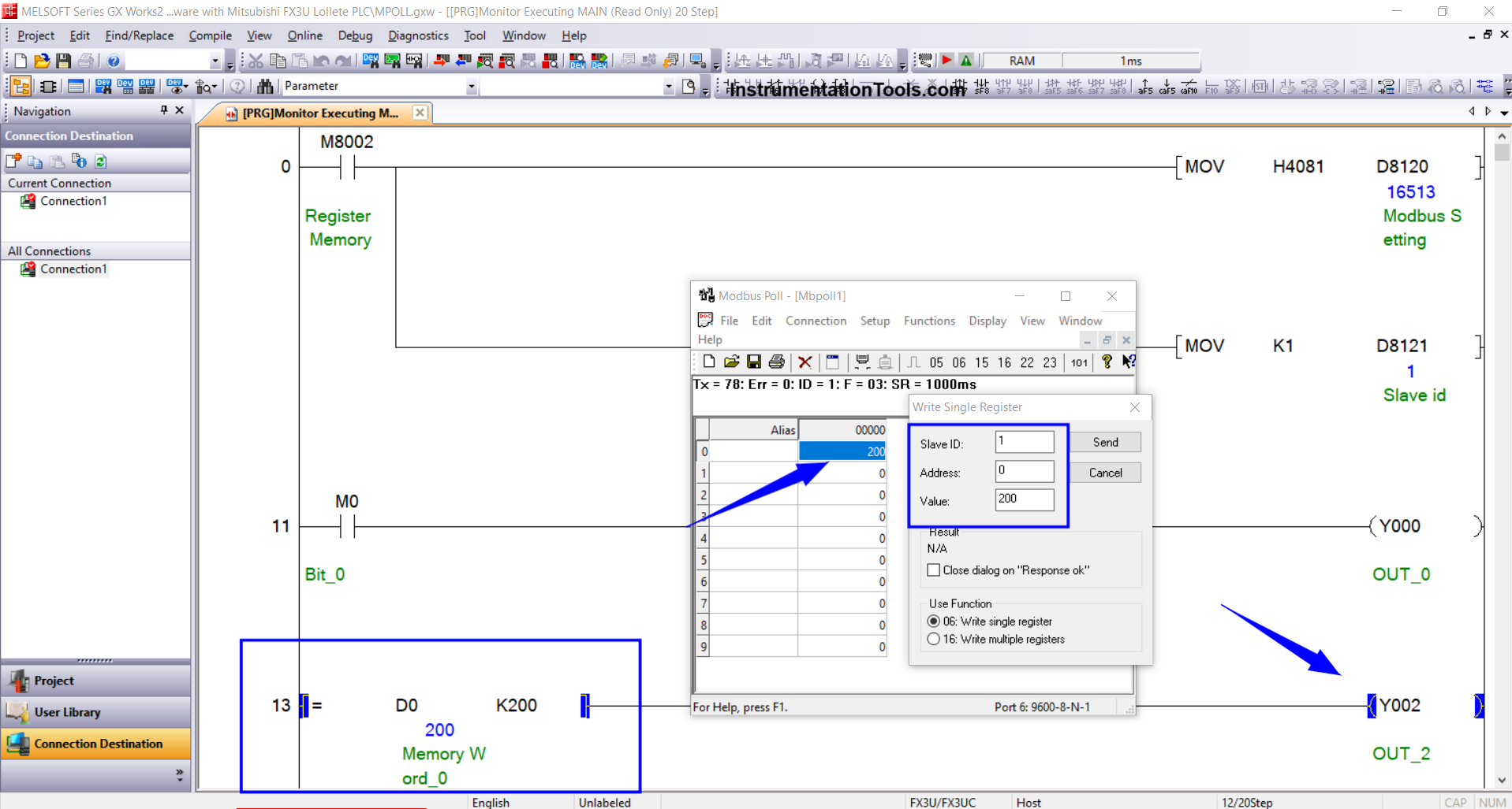
1. Create the Following Program
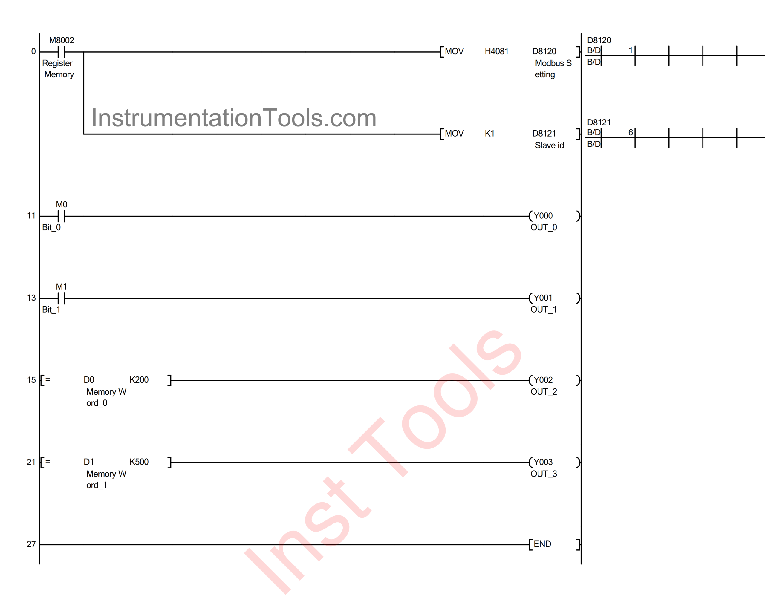
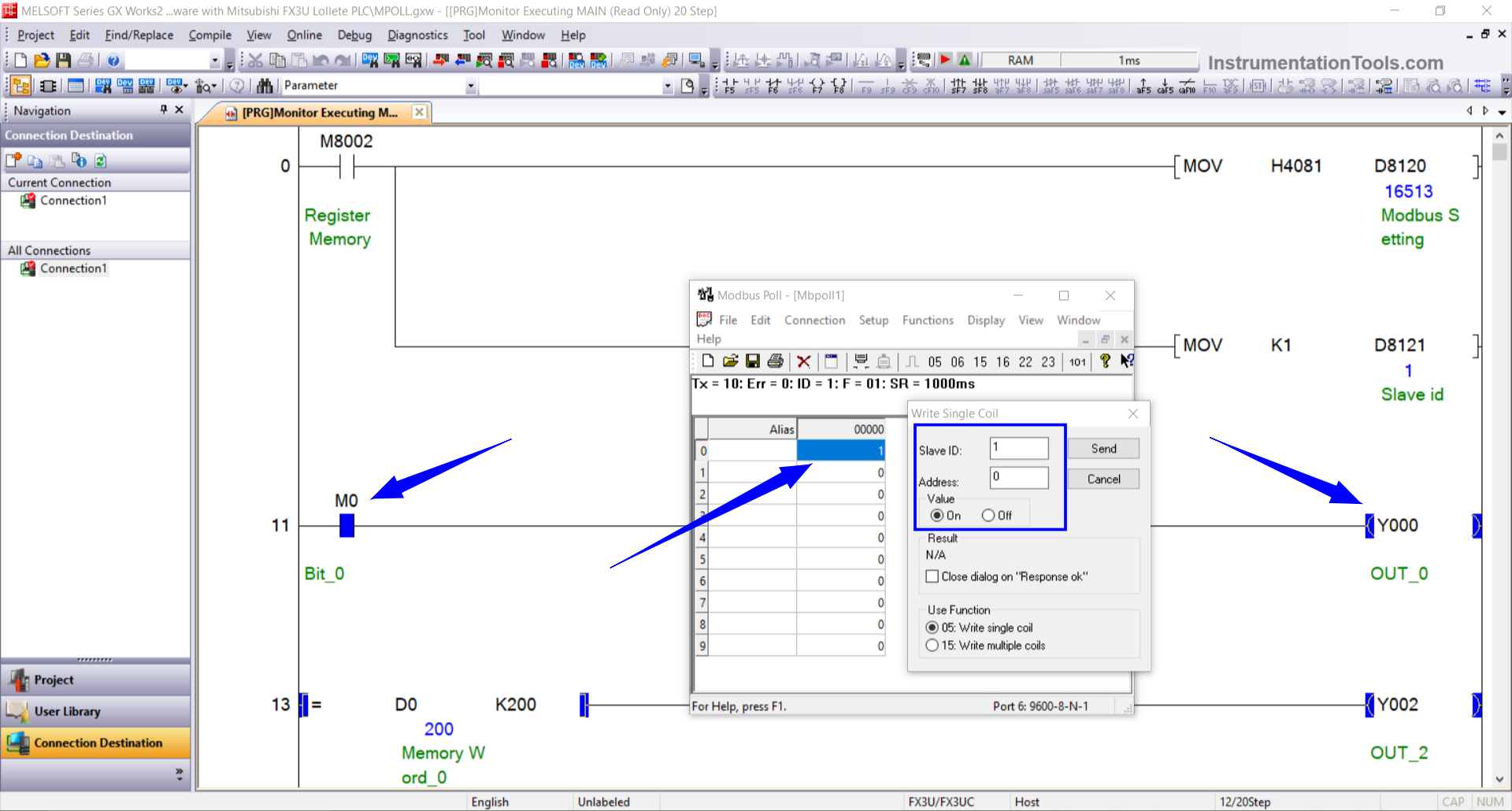
This program sets the PLC memory registers when used as a Slave. The bit memory Bit_0 (M0) and the word memory Memory_Word_0 (D0) will be controlled via Modbus Poll software.
When the NO contact of the Register Memory (M8002) is ON, the MOV instruction will transfer the value H4081 to the word memory Modbus Setting (D8120) and K1 to the word memory Slave ID (D8121).
When the NO contact Bit_0 (M0) is in a HIGH state, the output OUT_0 (Y000) will turn ON.
When the value in the word memory Memory_Word_0 (D0) equals “200”, the output OUT_2 (Y002) will turn ON.
2. Open Device Manager
Check that the communication port (e.g., COM5) is detected. Make sure the communication parameters are set as follows:
- Baudrate: 38400 bps
- Data Bits: 7
- Parity: Even
- Stop Bit: 1
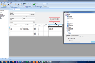
3. Open GX Works2
Go to Connection Detection → select Connection1 and configure the connection parameters:
- Interface: Serial USB (RS-232C)
- COM Port: Use the detected port (e.g., COM5)
- Transmission Speed: 38.4 Kbps
- Data Bits / Parity / Stop Bits: 7 / Even / 1
Run the Connection Test and ensure the message “Successfully Connected with the FX3U/FX3UC CPU” appears.
4. Transfer the Program to the PLC
Once the connection is verified:
Go to Online → Write to PLC
Select Parameter + Program → Click Execute to download the program and configuration to the PLC memory.
5. Start Online Monitoring
Finally, click the Start Monitoring/Start Monitoring (All Windows) icon to run GX Works2 in Online Monitoring mode.
Modbus Poll Software Settings
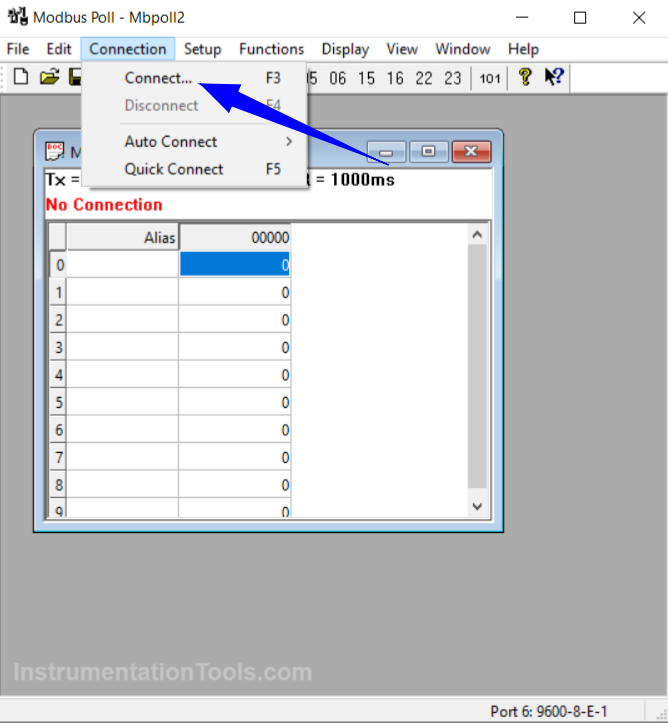
1. Open Modbus Poll Software
Click Connection → Click Connect, or press F3.
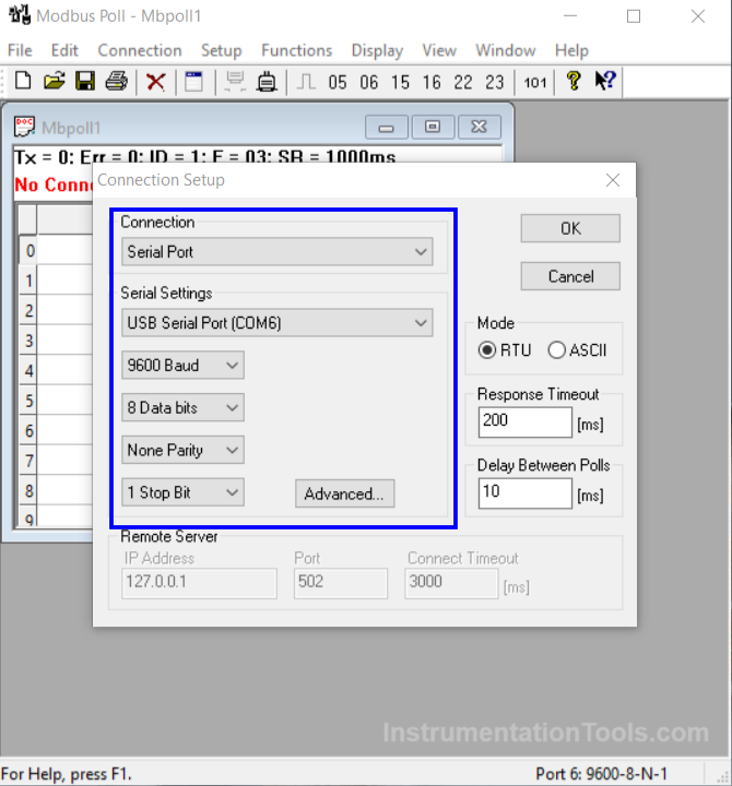
2. Configure the Connection:
- Connection: Serial Port
- Serial Settings: COM 6
- Baudrate: 9600
- Data Bits: 8
- Parity: None
- Stop Bit: 1
- Mode: RTU
- Response Timeout: 200 ms
Click OK.
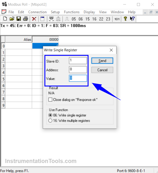
3. Sending Data from Modbus Poll
To send data, enter the value in the Modbus Poll Address field.
Set the value, Address: 0, Slave ID: 1 → Click Send. The data entered will automatically be received by the PLC and can be monitored in GX Works2.
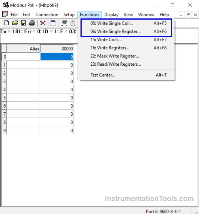
4. Changing the Data Type
To change the type of data sent, open the Function menu → select 06: Write Single Register to send decimal data, or select 05: Write Single Coil to send bit data.
Simulation Result
1. Single coil simulation result
2. Holding register simulation result
Read Next:
- Read Mitsubishi PLC Analog Input and Display in HMI
- Field Transmitter Communication Troubleshooting
- How To Map Mitsubishi Analog Inputs on Weintek HMI?
- How is Modbus used in Industrial Networking?
- Analog Voltage Control in PLC Using Weintek HMI