This article discusses how to convert Analog Input data on the Mitsubishi FX3U PLC into a range of 0–100%. This process is called scaling. Scaling in PLC programming is the process of converting sensor input values (usually in raw numeric form, known as resolution) into values that correspond to physical units or human-readable formats, such as temperature, pressure, or percentage.
Program Objective
To convert analog input values into a 0–100% scale, a scaling process is required using the following formula:
Percentage (%) = (Analog Input Value × 100) ÷ 4095
The number 4095 represents the maximum value of the 12-bit resolution analog input on the Mitsubishi FX3U Lollete PLC.
Programming Steps
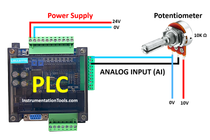
1. Reading Analog Input Data:
The analog input value is read using the RD3A instruction, which retrieves data from the analog module at channel “0/K0” with the data address “1/K1”.
2. Multiplication by 100:
The value obtained from the analog input is multiplied by 100 using the DMUL (Double Multiply) instruction to prepare the data for percentage scaling.
3. Division by Maximum Resolution (4095):
The result of the multiplication is divided by 4095 using the DDIV (Double Divide) instruction, resulting in a final value in percentage (%) format.
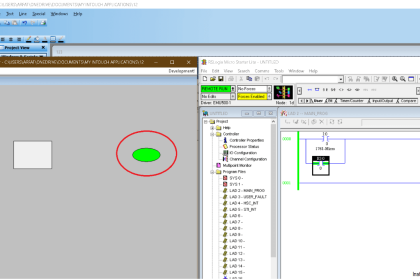
Simulation
In the video below, we show you how to do scaling in a Mitsubishi PLC.
Analog Scaling in Mitsubishi PLC
IO Mapping Details
| S.No. | Comment | Memory Bit | Memory Word |
|---|---|---|---|
| 1 | AI SCALING | M0 | |
| 2 | REGISTER CONTACT AI | M8011 | |
| 3 | AI | D0 | |
| 4 | AI*OUT HIGH | D4 | |
| 5 | OUTPUT | D8 |
Scaling Analog Input to 0-100%
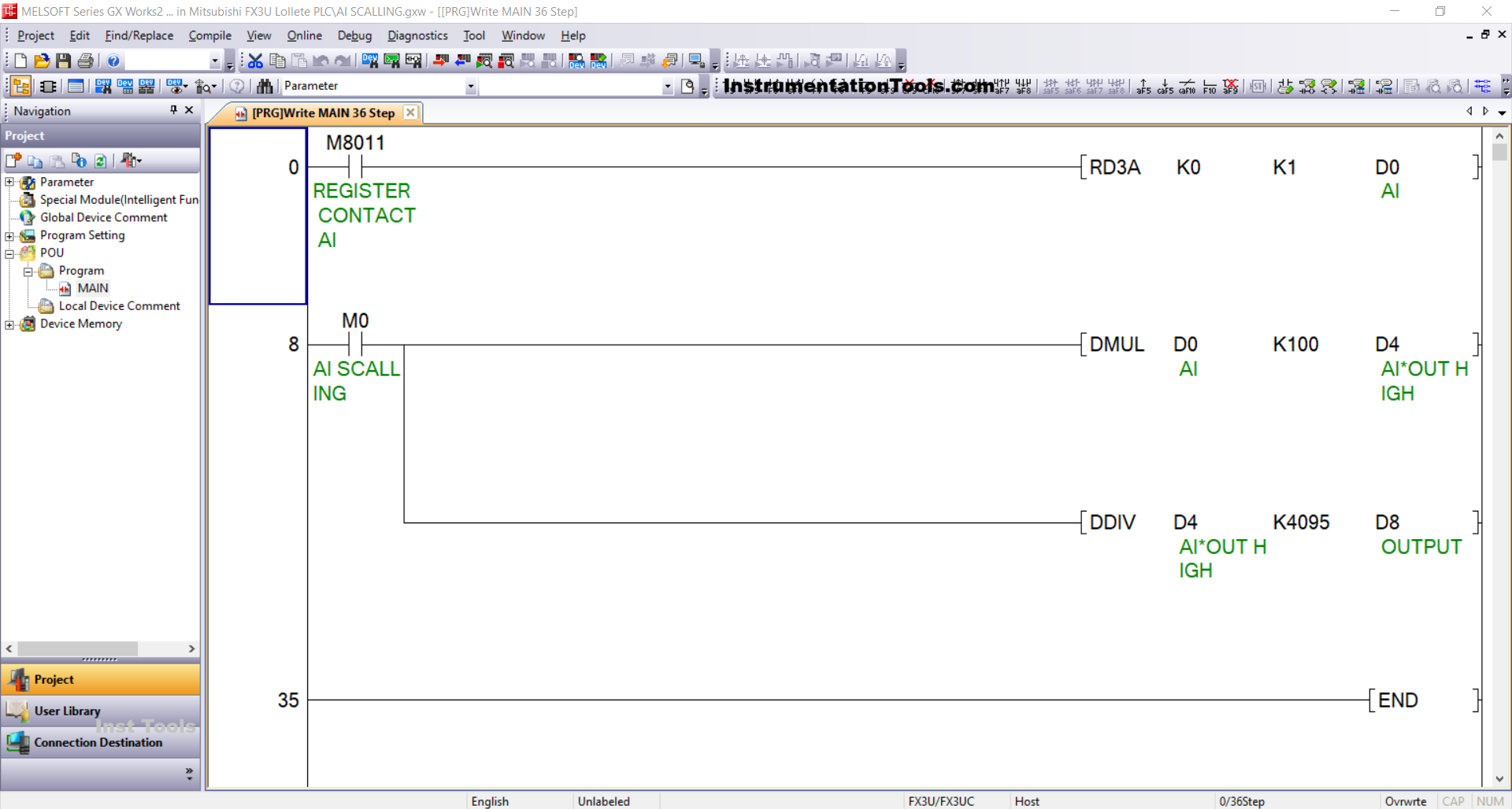
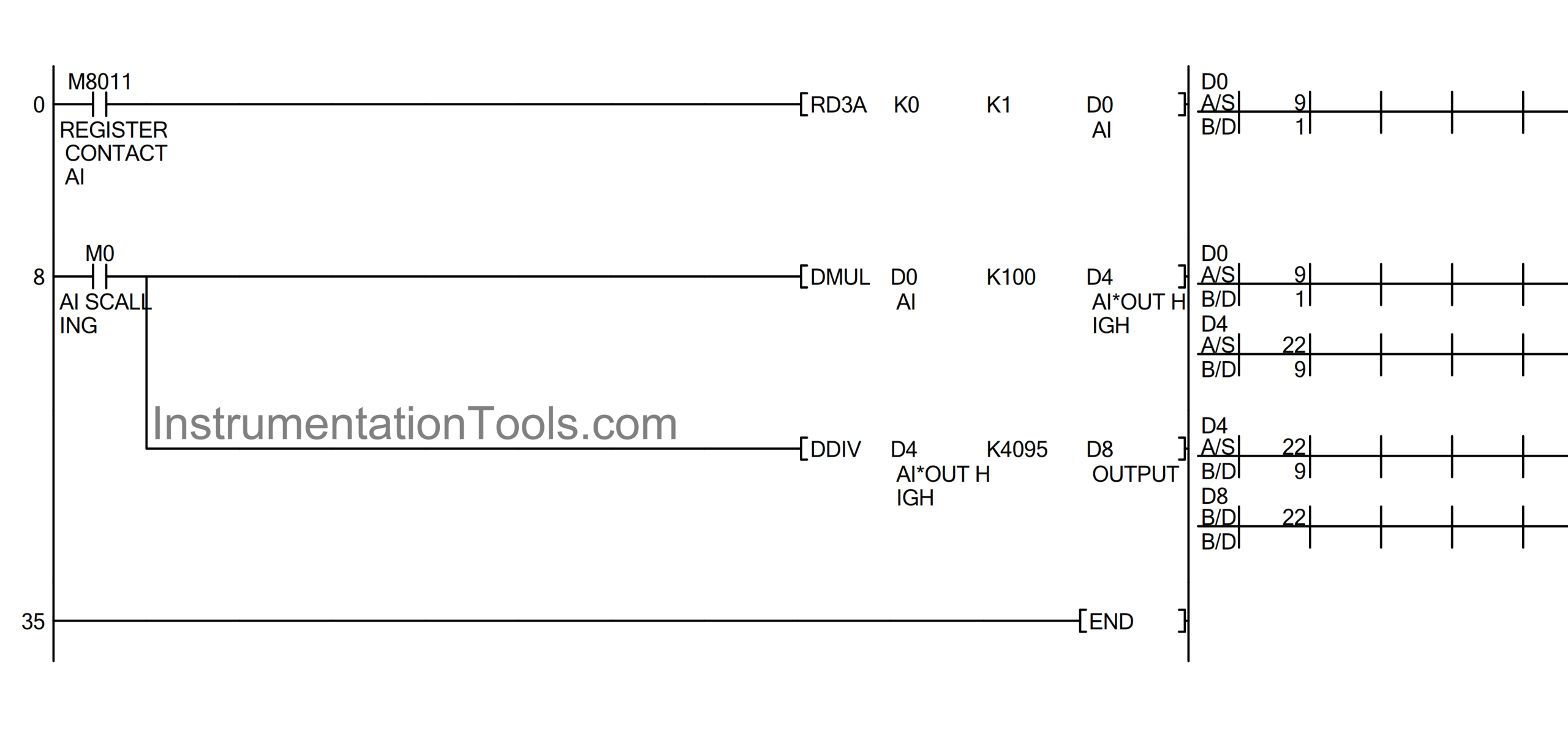
RUNG 0
In this rung, when the NO (Normally Open) contact of REGISTER CONTACT AI (M8011) is in a HIGH state, the RD3A instruction will read the analog input value from address “AD1” or “K1”. The analog input data will then be stored in memory word AI (D0).
RUNG 8
In this rung, when the NO contact of memory bit AI SCALING (M0) is in a HIGH state, the DMUL instruction will multiply the data in memory word AI (D0) by the value “100” and store the result in memory word AI*OUT HIGH (D4).
Next, the DDIV instruction will divide the data in memory word AI*OUT HIGH (D4) by the value “4095” and store the final result in memory word OUTPUT (D8).
Read Next:
- How does a PLC do the Scaling for a Sensor?
- PLC Program for Control Valve Scaling
- Ladder Logic for Sensor Scaling with Offset
- Analog Input in Mitsubishi FX3U LOLLETTE PLC
- Curtain Control Example PLC Programming Solution