This article will discuss an automatic fruit sorting system using the Siemens PLC and TIA-Portal software. This system is designed to sort fruits based on weight and color. The fruits to be processed are categorized into three different colors: Red, Yellow, and Green. Only fruits that are Green in color and meet the specified weight standards will be collected. The sorting process begins with the separation of fruits that do not meet the weight standards before proceeding to the color-based sorting stage. The system is equipped with an indicator alarm that activates when the number of fruits collected reaches a predetermined limit.
Program Objective
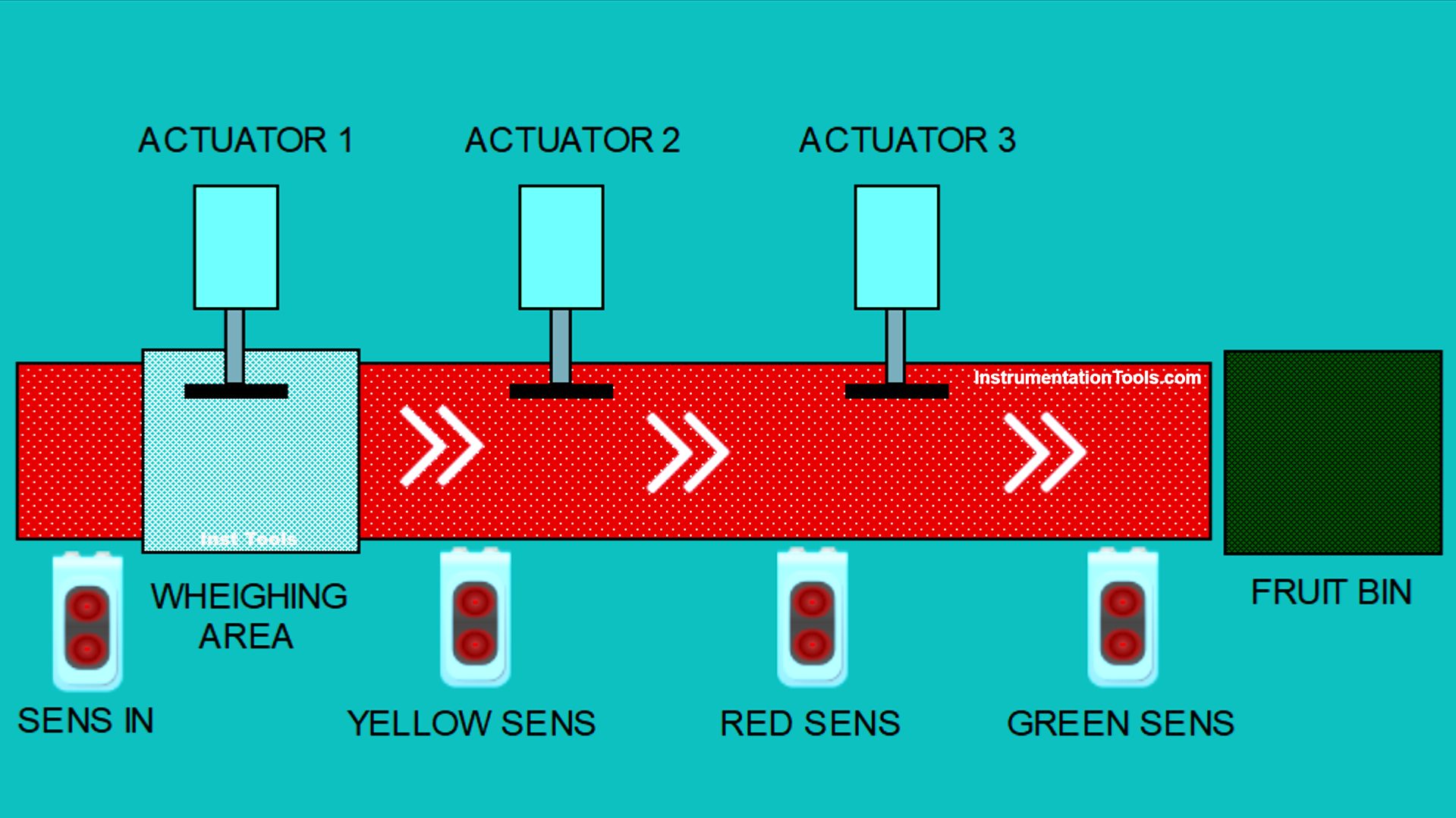
Steps of the Fruit Sorting System Based on Weight and Color:
The conveyor will carry the fruits to be sorted.
Fruit Sorting Based on Weight:
- Weight sensors (Load Cells) installed under the conveyor will measure the weight of the fruits.
- The system, after receiving data from the weight sensors, will compare the data. If the weight does not exceed 7 grams, the fruit will be considered to meet the standard.
- An actuator will separate fruits that do not meet the criteria by pushing them out of the conveyor line.
Fruit Sorting Based on Color:
- Color sensors will detect the specific colors of the fruits, such as Green, yellow, and Red, that indicate the level of ripeness.
- Fruits with Red and Yellow colors will be separated using an actuator, while only Green-colored fruits will be collected.
End of the System Process:
- The system will count the number of fruits that have been collected.
- A warning alarm will activate if the number of collected fruits has reached the maximum limit of “30”.
Fruit Sorting by Weight and Color
Mapping Details
| S.No. | Comment | Input (I) | Output(Q) | Memory Words | Memory Bit | Timers |
| 1 | START | I0.0 | ||||
| 2 | STOP | I0.1 | ||||
| 3 | SENS_RED | I0.2 | ||||
| 4 | SENS_YELLOW | I0.3 | ||||
| 5 | SENS_GREEN | I0.4 | ||||
| 6 | SENS_IN | I0.5 | ||||
| 7 | RESET_COUNTER | I0.6 | ||||
| 8 | LS_ACT2 | I0.7 | ||||
| 9 | LS_ACT3 | I1.0 | ||||
| 10 | CONVEYOR | Q0.0 | ||||
| 11 | ACTUATOR_1 | Q0.1 | ||||
| 12 | ACTUATOR_2 | Q0.2 | ||||
| 13 | ALARM_MAX | Q0.3 | ||||
| 14 | ACTUATOR_3 | Q0.4 | ||||
| 15 | TIMER_WEIGHING | DB1 | ||||
| 16 | COUNT_FRUIT | MW0 | ||||
| 17 | WEIGHT_FRUIT | MW1 | ||||
| 18 | SYSTEM_ON | M4.0 | ||||
| 19 | PAUSE_SYSTEM | M4.1 | ||||
| 20 | TEMP_SENS_IN | M4.2 | ||||
| 21 | TEMP_SENS_RED | M4.3 | ||||
| 22 | TEMP_SENS_YELLOW | M4.4 | ||||
| 23 | TEMP_LS_ACT2 | M4.5 | ||||
| 24 | TEMP_LS_ACT3 | M4.6 | ||||
| 25 | TEMP_SENS_GREEN | M4.7 |
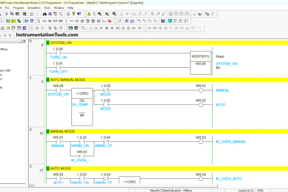
Siemens PLC Project
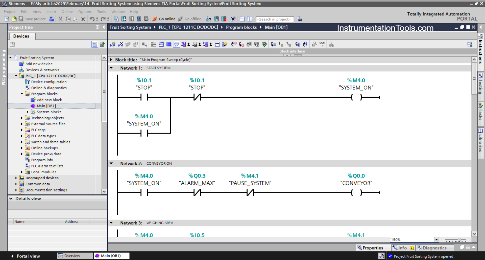
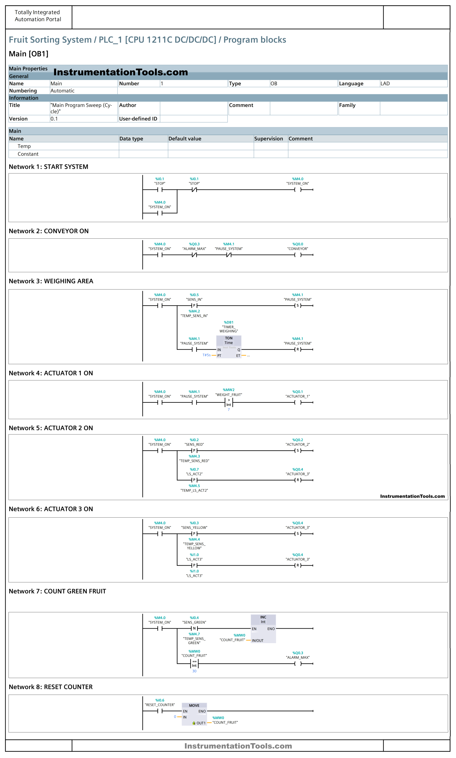
NETWORK 1 (START SYSTEM)
In this network, the memory bit SYSTEM_ON (M4.0) will be in the HIGH state when the PB_START (I0.0) button is Pressed. Even though the PB_START (I0.0) button has been Released, the memory bit SYSTEM_ON (M4.0) will remain in the HIGH state. Because it uses Latching
When the PB_STOP (I0.1) button is Pressed, the memory bit SYSTEM_ON (M4.0) will be in the LOW state.
NETWORK 2 (CONVEYOR ON)
In this network, if the NO contact of the memory bit SYSTEM_ON (M4.0) is in the HIGH state, then the CONVEYOR (Q0.0) output will be ON.
When the NC contact of ALARM_MAX (Q0.3) or PAUSE_SYSTEM (M4.1) is in the HIGH state, the CONVEYOR (Q0.0) output will be OFF.
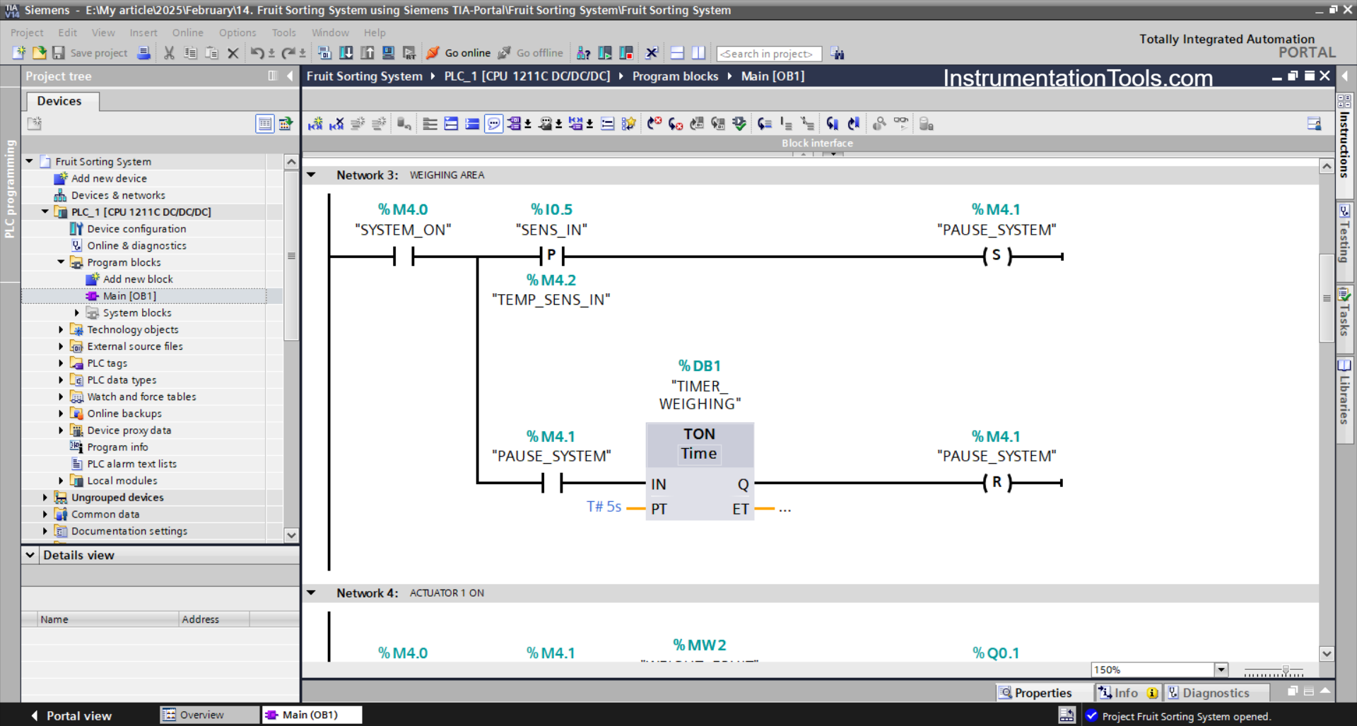
NETWORK 3 (WEIGHING AREA)
In this network, the memory bit PAUSE_SYSTEM (M4.1) will be in the HIGH state if the NO contact of the memory bit SYSTEM_ON (M4.0) and the SENS_IN (I0.5) sensor are in the HIGH state.
Even though the SENS_IN (I0.5) sensor is in the LOW state, the memory bit PAUSE_SYSTEM (M4.1) will remain in the HIGH state. Because it uses the SET Output instruction
Next, the TIMER_WEIGHING (DB1) timer will start counting up to 5 seconds, and after the timer has finished counting, the memory bit PAUSE_SYSTEM (M4.1) will be in a LOW state because the RESET Output Instruction has been triggered by the TIMER_WEIGHING (DB1) timer.
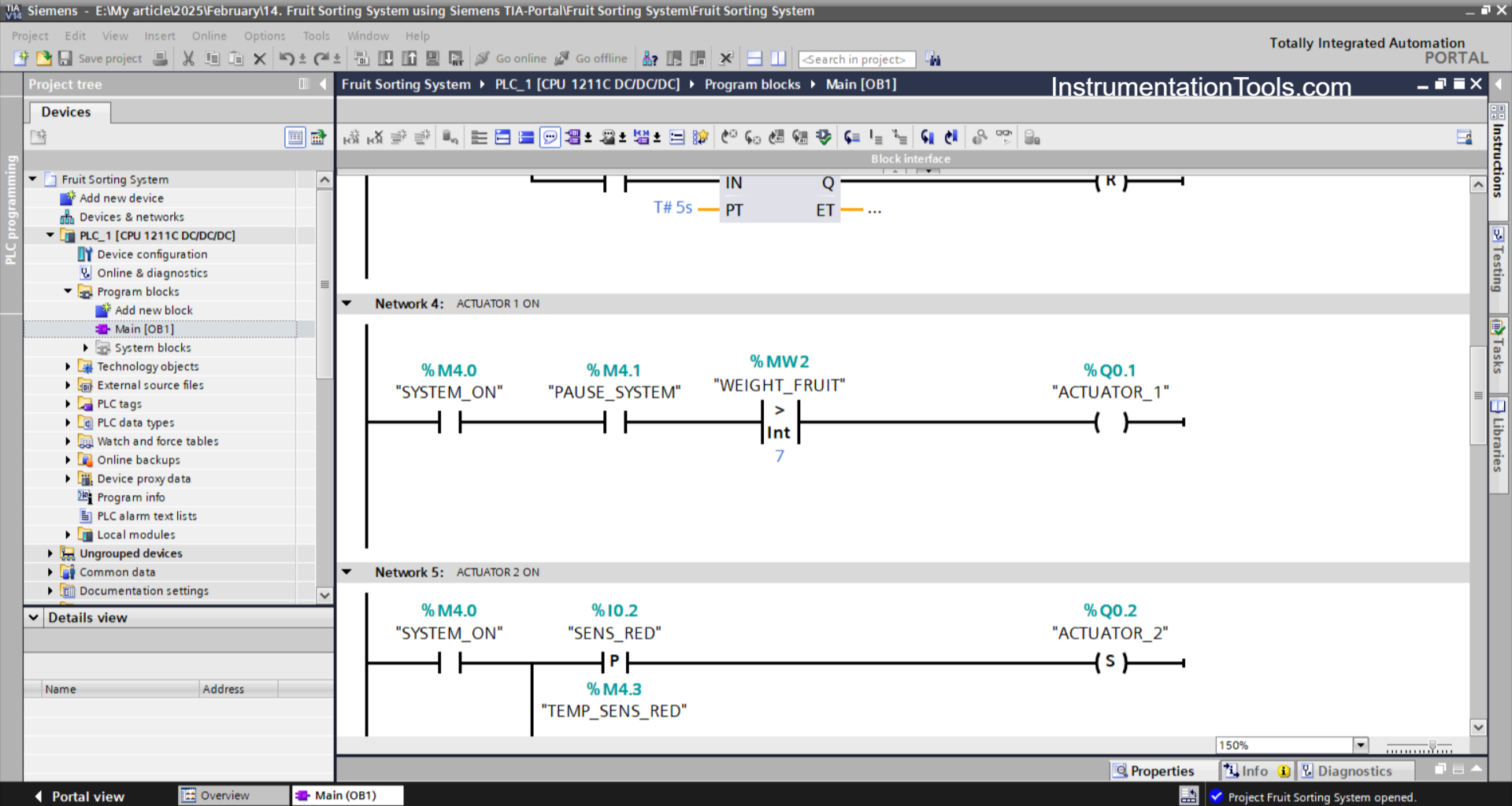
NETWORK 4 (ACTUATOR 1 ON)
The output ACTUATOR_1 (Q0.1) will be ON if the NO contacts of the memory bits SYSTEM_ON (M4.0) and PAUSE_SYSTEM (M4.1) are in the HIGH state and the value in the memory word WEIGHT_FRUIT (MW1) is Greater Than “7”.
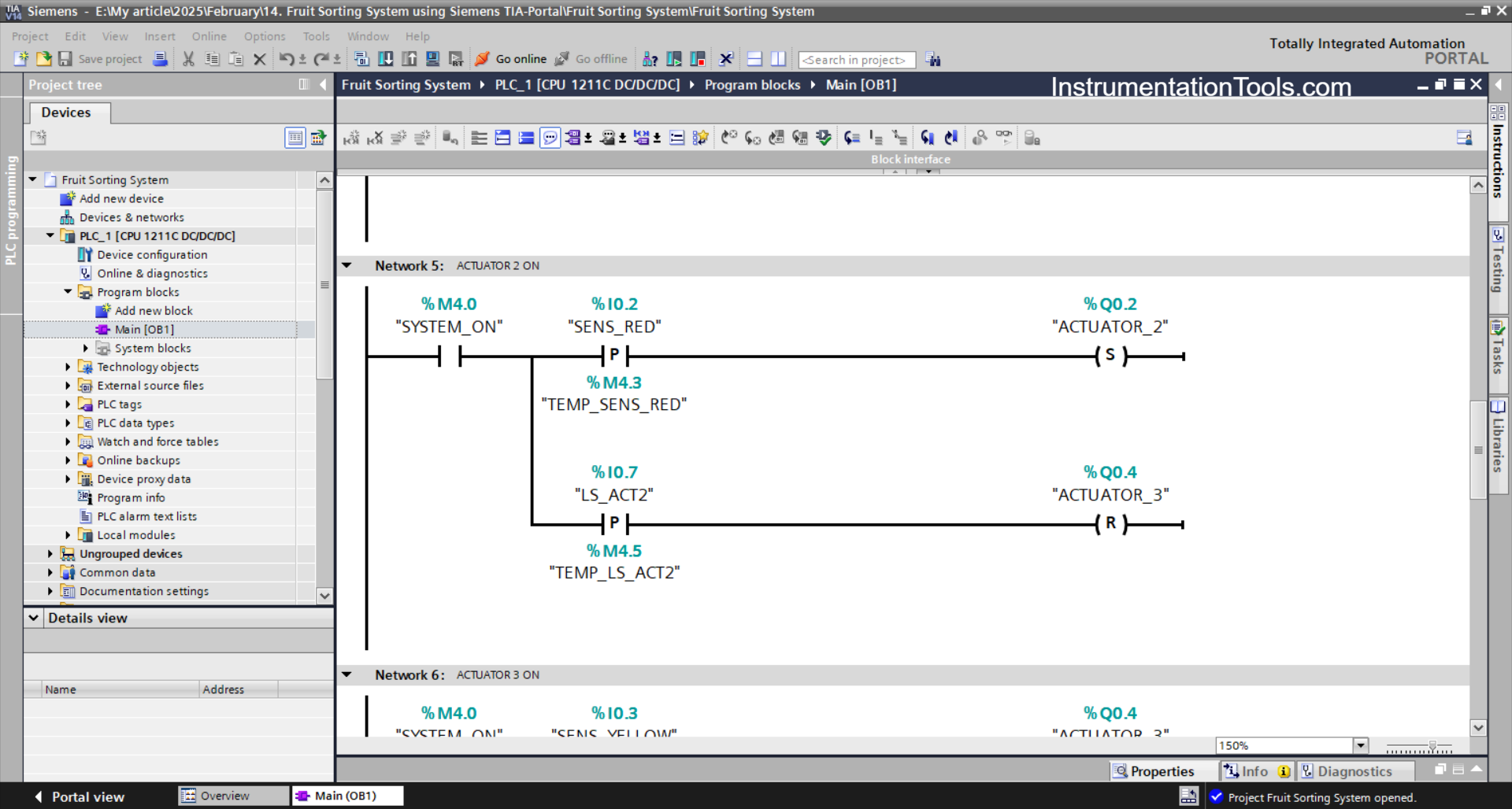
NETWORK 5 (ACTUATOR 2 ON)
The ACTUATOR_2 (Q0.2) output will be ON when the NO contact of the memory bit SYSTEM_ON (M4.0) and the SENS_RED (I0.2) sensor are in the HIGH state.
The ACTUATOR_2 (Q0.2) output will be OFF when the NO contact of the limit switch LS_ACT2 (I0.7) is in the HIGH state.
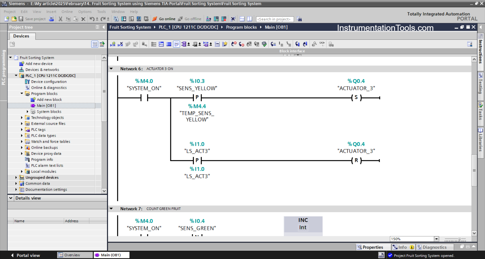
NETWORK 6 (ACTUATOR 3 ON)
The ACTUATOR_3 (Q0.4) output will be ON when the NO contact of the memory bit SYSTEM_ON (M4.0) and the SENS_YELLOW (I0.3) sensor are in the HIGH state.
The ACTUATOR_3 (Q0.4) output will be OFF if the NO contact of the limit switch LS_ACT3 (I1.0) is in the HIGH state.
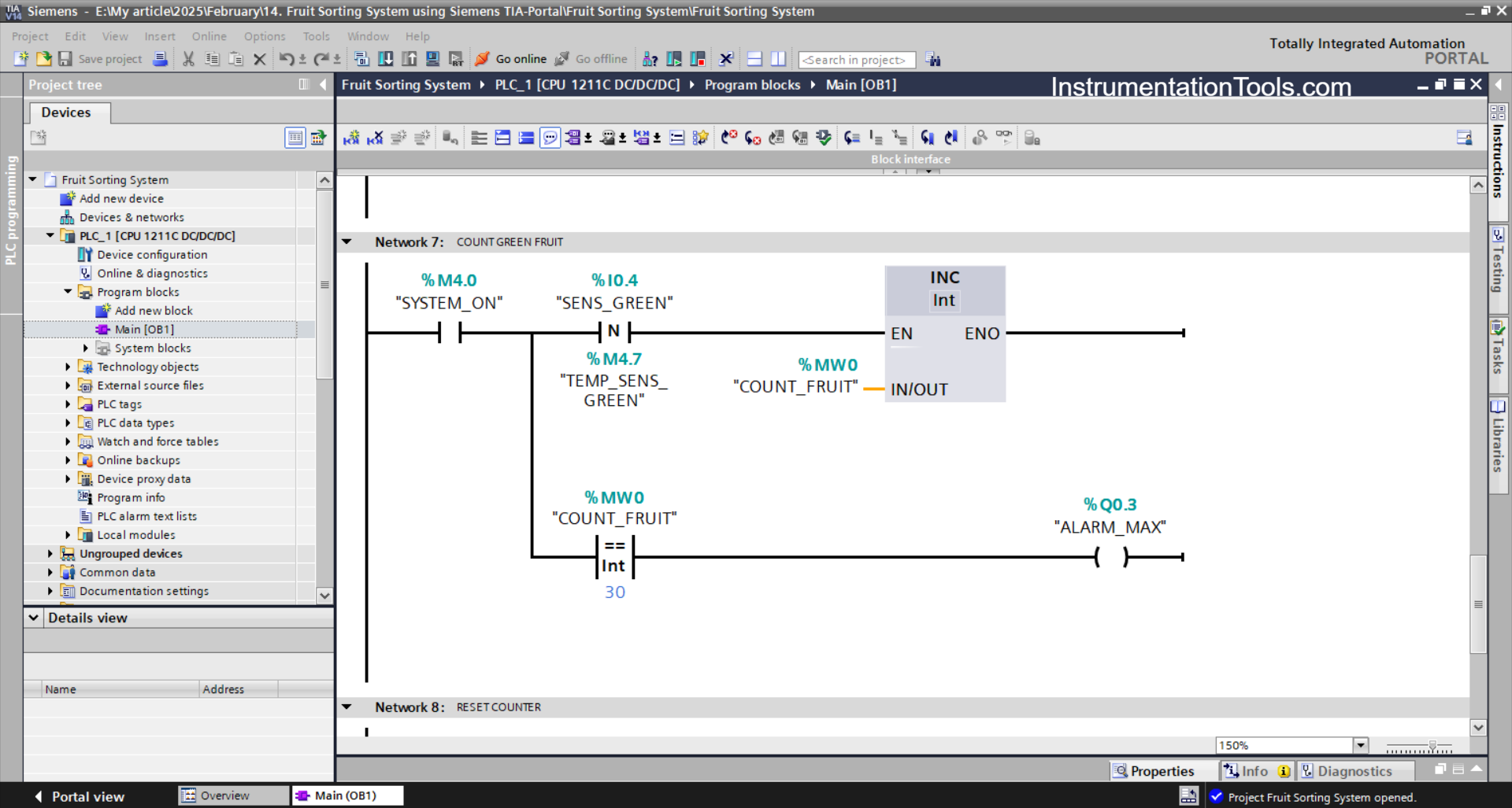
NETWORK 7 (COUNT GREEN FRUIT)
Because it uses the ADD instruction, when the NO contact of the memory bit SYSTEM_ON (M4.0) and the SENS_GREEN (I0.4) sensor are in the HIGH state, the value in the memory word COUNT_FRUIT (MW0) will increase (+1).
The ALARM_MAX (Q0.3) output will be OFF when the value in the memory word COUNT_FRUIT (MW0) is Equal to “30”.
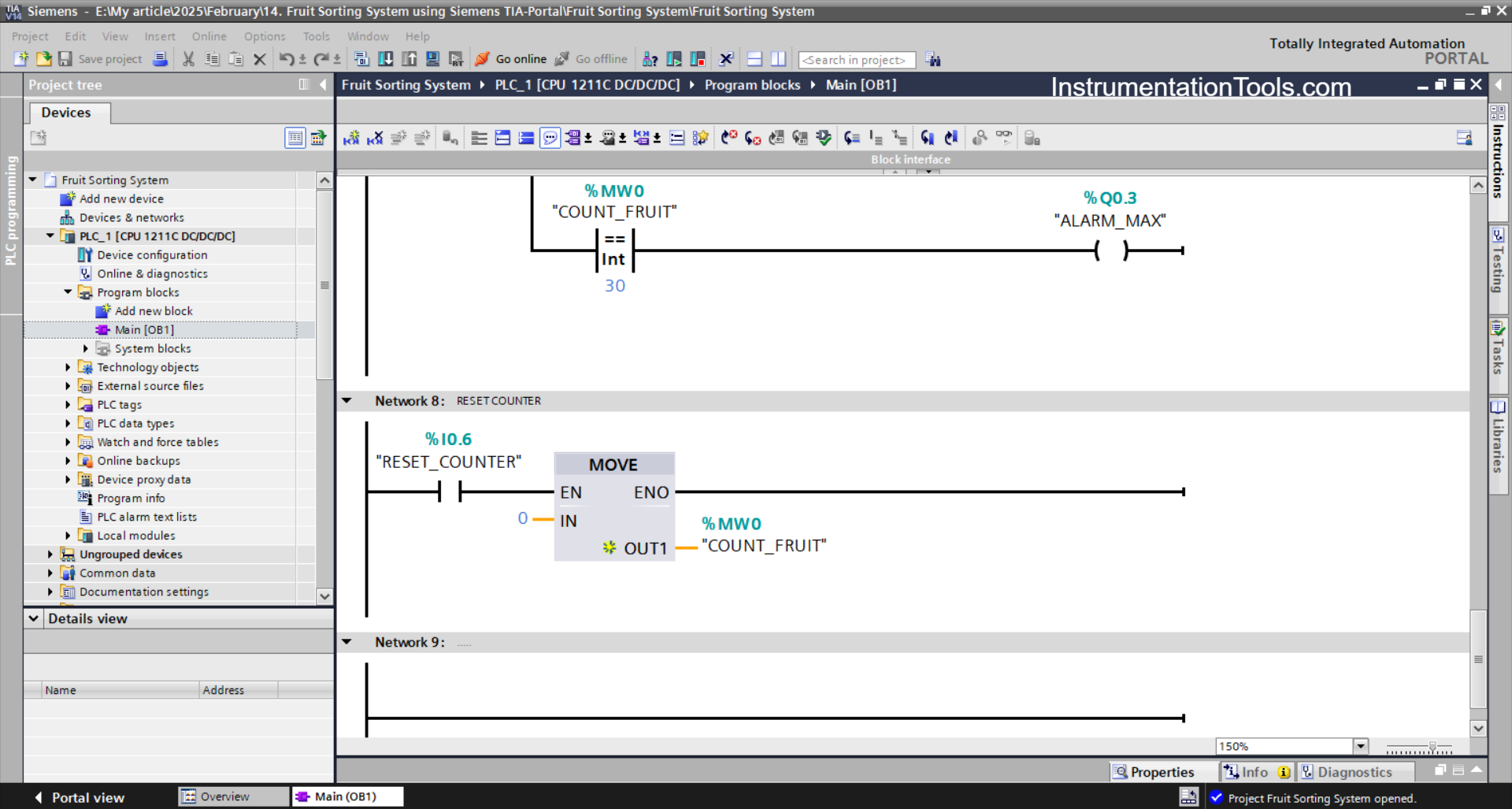
NETWORK 8 (RESET COUNT GREEN FRUIT)
The value in the memory word COUNT_FRUIT (MW0) will be zero “0” when the RESET_COUNTER (I0.6) button is Pressed.
The MOV instruction moves the zero value “0” to the memory word COUNT_FRUIT (MW0).
Read Next:
- PLC Program with Calculation Function
- Conveyor Sorting System with Color Detection
- CX-Programmer Products Sorting & Counting
- PLC Based Product Sorting Machine System
- PLC Sorting & Distribution of Boxes by Height