Inst ToolsInst ToolsInst Tools
  • Courses
  • Automation
    • PLC
    • Control System
    • Safety System
    • Communication
    • Fire & Gas System
  • Instrumentation
    • Design
    • Pressure
    • Temperature
    • Flow
    • Level
    • Vibration
    • Analyzer
    • Control Valve
    • Switch
    • Calibration
    • Erection & Commissioning
  • Interview
    • Instrumentation
    • Electrical
    • Electronics
    • Practical
  • Q&A
    • Instrumentation
    • Control System
    • Electrical
    • Electronics
    • Analog Electronics
    • Digital Electronics
    • Power Electronics
    • Microprocessor
  • Request
Search
  • Books
  • Software
  • Projects
  • Process
  • Tools
  • Basics
  • Formula
  • Power Plant
  • Root Cause Analysis
  • Electrical Basics
  • Animation
  • Standards
  • 4-20 mA Course
  • Siemens PLC Course
Reading: PID in Studio 5000
Share
Notification Show More
Font ResizerAa
Inst ToolsInst Tools
Font ResizerAa
  • Courses
  • Design
  • PLC
  • Interview
  • Control System
Search
  • Courses
  • Automation
    • PLC
    • Control System
    • Safety System
    • Communication
    • Fire & Gas System
  • Instrumentation
    • Design
    • Pressure
    • Temperature
    • Flow
    • Level
    • Vibration
    • Analyzer
    • Control Valve
    • Switch
    • Calibration
    • Erection & Commissioning
  • Interview
    • Instrumentation
    • Electrical
    • Electronics
    • Practical
  • Q&A
    • Instrumentation
    • Control System
    • Electrical
    • Electronics
    • Analog Electronics
    • Digital Electronics
    • Power Electronics
    • Microprocessor
  • Request
Follow US
All rights reserved. Reproduction in whole or in part without written permission is prohibited.
Inst Tools > Blog > PLC Tutorials > PID in Studio 5000

PID in Studio 5000

Learn how to implement PID in Studio 5000 for precise process control in PLC programming using function blocks for automation.

Last updated: March 16, 2025 6:20 pm
Viral Nagda
PLC Tutorials
No Comments
Share
6 Min Read
SHARE

PID is a very important function in PLC programming. Not only PLC, but PID is an algorithm that is used in many control devices like embedded controllers too. PID is a function which helps to keep the process variable steady around the setpoint. Due to this, the processes which require a precise process variable for working in their function, use PID blocks in their programming. One of the most widely used automation software in the market is Studio 5000 of Rockwell Automation. In this post, we will see how to use the PID block in Studio 5000.

Contents
PID Function BlocksPID in Studio 5000

PID Function Blocks

Studio 5000 has two types of PID function blocks – basic and enhanced. The enhanced version or PIDE is available only in functional block diagram language, whereas the basic version or PID is available only in ladder logic. For our study, we will see a basic version for simple understanding.

PID in Studio 5000

Let us write the logic step by step:

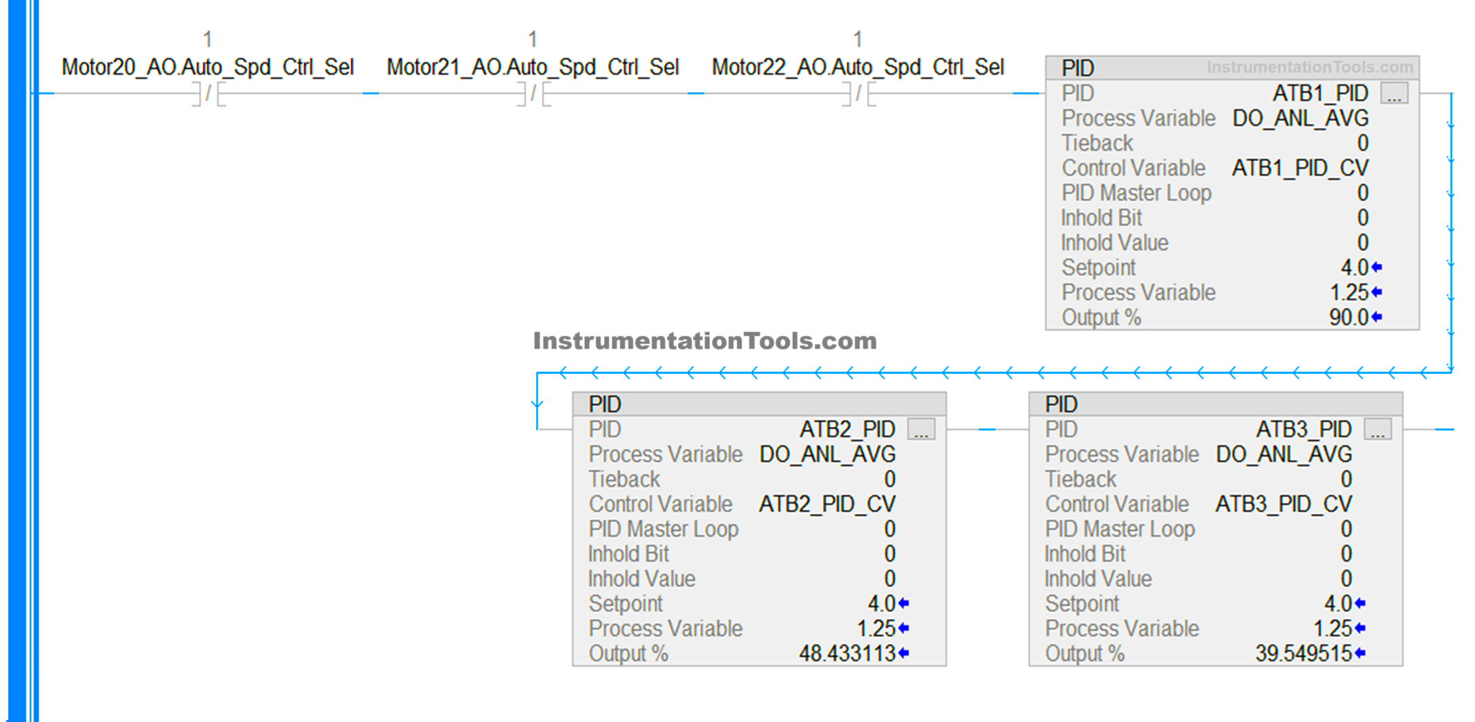
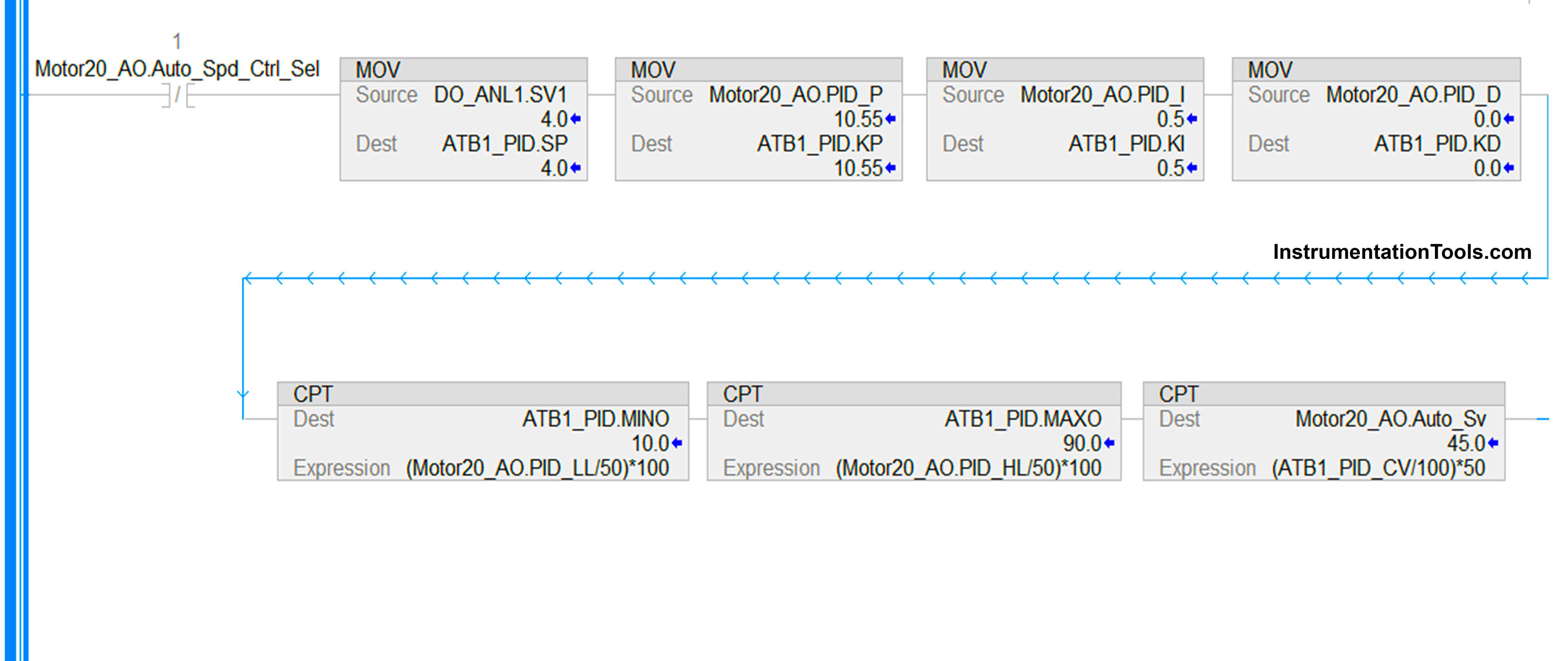
  1. As we are using a basic PID block, we will require ladder logic for programming. Refer to the below image. You can get this block from the section – special. As you can see, I have taken three PID blocks, but we will concentrate on only one – ATB1_PID. Any PID block has the following connections – setpoint, process variable, reset, PID values, and control variable/output. Similarly, even this block in Studio 5000 has all these connections to its block.
InstrumentationTools.com
  1. Now, let us first understand the terms we will use for our programming:

A] PID – Name of the block.

B] Process variable– Input variable to PID.

C] Control variable– Output variable from PID.

D] Setpoint (.SP)– Setpoint of PID.

E] Output %– Output of PID in percentage.

F] Proportional value (.KP)– KP value to be fed in PID.

G] Integral value (.KI)– KI value to be fed in PID.

H] Derivative value (.KD)– KD value to be fed in PID.

I] Low limit value (.MINO)– Minimum output of PID which will limit the actual output.

J] High limit value (.MAXO)– Maximum output of PID which will limit the actual output.

  1. As we have now understood the general terms that we will use for our program, let us go and program the PID now. We have already taken the block as we saw earlier. ATB1_PID is the name of the PID block taken. DO_ANL_AVG is the process variable which is given to PID for feedback. ATB1_PID_CV is the control variable which will be given by PID as output. You can directly link these variables in these connections. Remaining connections must be moved by a move block which we will see in the next point.
  2. Refer to the below image. We use move blocks to communicate between external variables and PID connections. We move the variables to the following terms we discussed before – .SP, .KP, .KI, .KD, .MINO, and .MAXO. Also, as we are using a VFD in our example and whose frequency needs to be varied between 0-50 Hz, we will divide the control variable output from PID by 100, multiply the result by 50, and then move to our analog output variable. In the program, you will be required to scale it further between actual raw counts the PLC gives in an analog output.
Studio 5000 PID function blocks
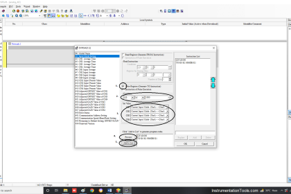
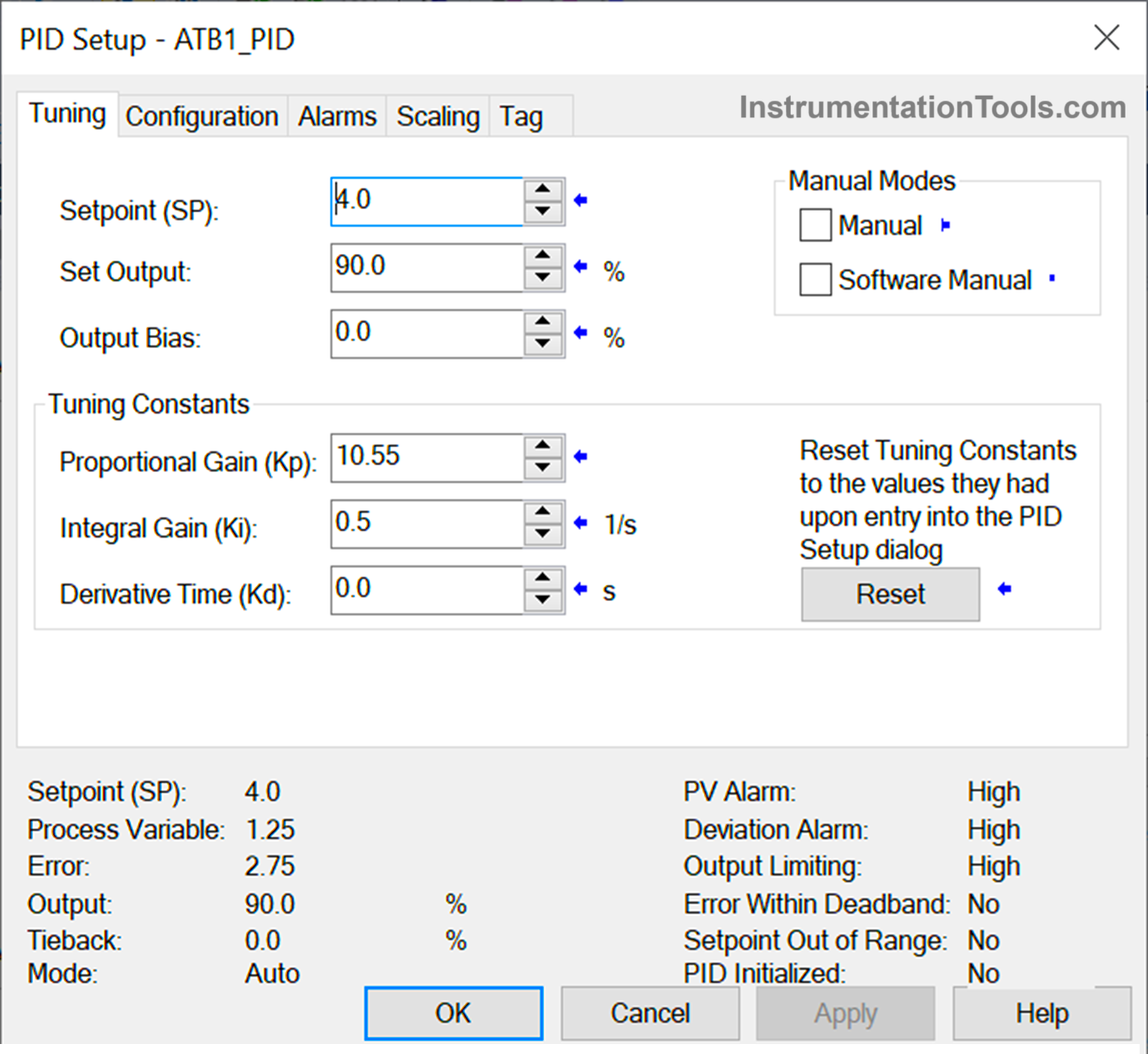
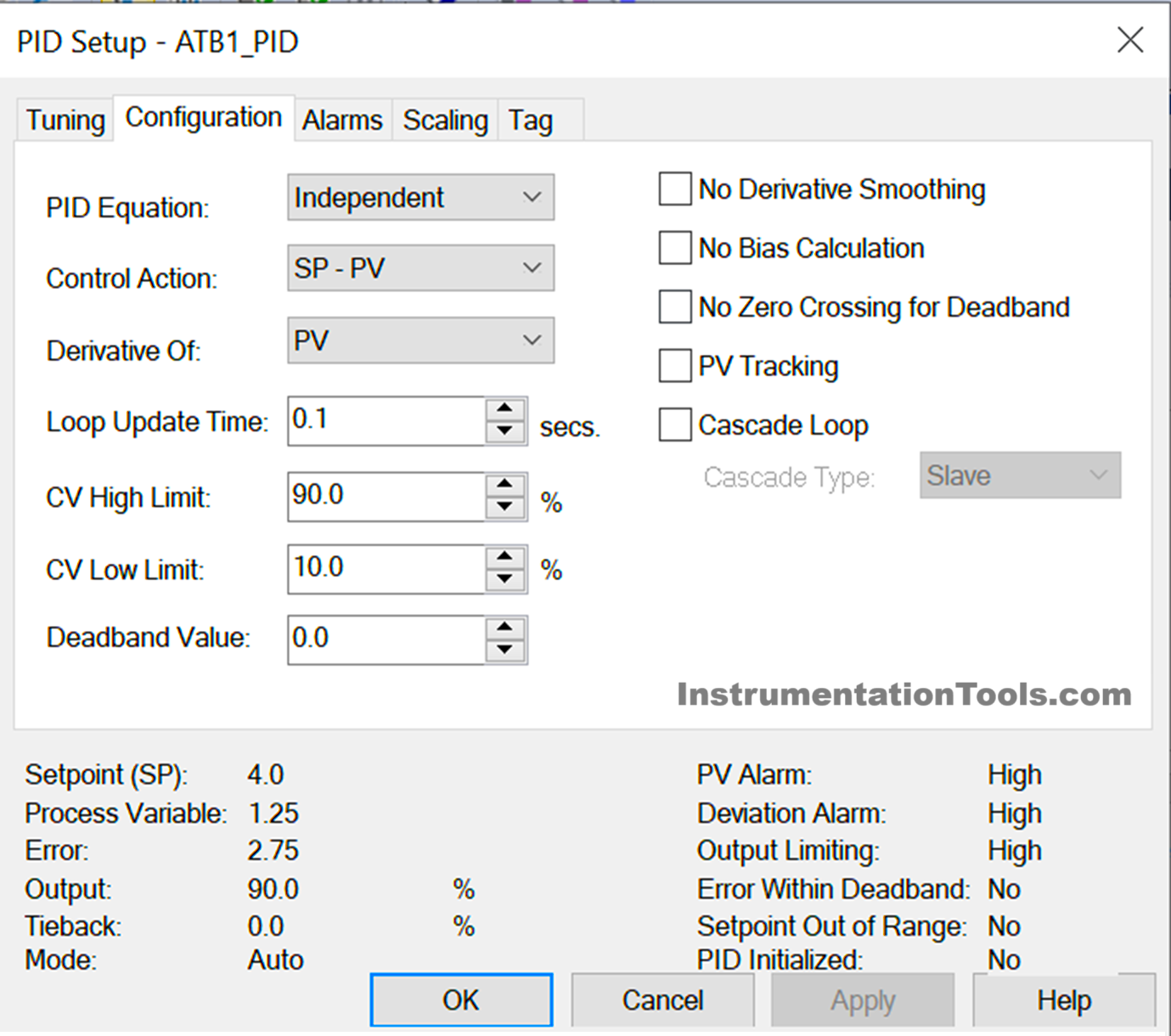
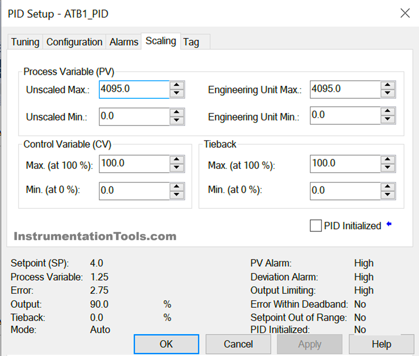
  1. Now comes the step to configure the PID block. Refer to the below images in sequence. In the first image, we see the tuning parameters which are derived from the logic we wrote in the previous step. When you go online, you have to press the reset button if the values are not taken or the PID is not giving output. In the second image, you see the configuration parameters where you have to generally select the control action – SP-PV or PV-SP. SP-PV means heating action, where the output increases if PV is below SP and decreases if PV goes more than SP. PV-SP works in a reverse direction as a cooling action. You will be required to set the loop update time once when online, after seeing the performance of the output variation. 0.1 seconds is the best value to set here. In the third image, we see the scaling parameters which are derived from the logic we wrote in the previous step. Here, PV scaling is just required to enter its minimum and maximum values. Keep the unscaled and engineering values as same as possible.
PID Setup
PID Tuning and Configuration
PID Scaling
  1. Once this step has been done, your PID is now ready to work. Download the code in PLC and check it’s output by varying the input. You will be required to vary P,I and D parameters in runtime according to the performance.

In this way, we saw how to write PID in Studio 5000.

Read Next:

  • Studio 5000 PLC Program for Digital Alarm
  • PLC Program for Pumping and Draining System
  • Allen Bradley Studio 5000 Motor Running Hours
  • Produced Tags and Consumed Tags in Studio 5000
  • Allen Bradley PLC to PLC Communication Tutorial
Don't Miss Our Updates
Be the first to get exclusive content straight to your email.
We promise not to spam you. You can unsubscribe at any time.
Invalid email address
You've successfully subscribed !

Continue Reading

Difference between DCS, PLC, and RTU ?
FOR DO Statement in SCL Language
How-to do Security of SCADA Systems?
What is a Data Block? Global Data Blocks in PLC
How to Get a PLC Programming Job With NO Experience?
STAR-DELTA Auto And Manual Program using XG5000 Software
Share This Article
Facebook Whatsapp Whatsapp LinkedIn Copy Link
Share
Leave a Comment

Leave a Reply Cancel reply

Your email address will not be published. Required fields are marked *

Stay Connected

128.3kFollowersLike
69.1kFollowersFollow
210kSubscribersSubscribe
38kFollowersFollow

Categories

Explore More

PLC Electric Motor Interlocks
Learn about SCADA and HMI Systems
Operator Interface for SCADA System
What are AI, AO, DI, and DO? – Definition, Examples, Purpose
Motor Trip Logic using PLC Programming
Schneider PLC Programming Example for Beginners
PLC Program to Count Running Hours of any Equipment
Motor Control Signal Interface

Keep Learning

Two Tanks Filling using PLC

PLC Ladder Logic for Tanks Filling as per Priority

Siemens PLC Force LED

Forcing and Modifying PLC Logic

PLC Program for Controlling Sequence of Conveyors with Interlocking

PLC Program for Controlling Sequence of Conveyors with Interlock

A Typical Sequential Function Chart

What is Sequential Function Chart (SFC?)

Traces in TIA Portal

What is Trace Function in Tia Portal?

Key Facts About RS485 Industrial Network

Key Facts About RS485 Industrial Network

Search tank in Intouch Scada

Tank Filling and Emptying using Intouch Scada Script

How Engineers Effectively do Problem-solve and Troubleshoot

How Engineers Effectively do Problem-solve and Troubleshoot?

Learn More

PLC Program for Control Valve Scaling

PLC Program for Control Valve Scaling

Strain gage load cells

Load Cell Healthiness Checks

Free Download PLC Book

#10 PLC Best Practices – Assign Register Blocks by Function

Objective Questions of Building Fire and Gas Detectors

Objective Questions of Building Fire and Gas Detectors

SIS Failures and Reliability - Safety Instrumented Systems

SIS Failures and Reliability – Safety Instrumented Systems

Free Siemens PLC Training Course

Free Siemens PLC Training Course

Difference between Transmitter and Transducer with Examples

Difference between Transmitter and Transducer with Examples

What is Energy Monitoring System

What is Energy Monitoring System ?

Menu

  • About
  • Privacy Policy
  • Copyright

Quick Links

  • Learn PLC
  • Helping Hand
  • Part Time Job

YouTube Subscribe

Follow US
All rights reserved. Reproduction in whole or in part without written permission is prohibited.
Welcome Back!

Sign in to your account

Username or Email Address
Password

Lost your password?