Inst ToolsInst ToolsInst Tools
  • Courses
  • Automation
    • PLC
    • Control System
    • Safety System
    • Communication
    • Fire & Gas System
  • Instrumentation
    • Design
    • Pressure
    • Temperature
    • Flow
    • Level
    • Vibration
    • Analyzer
    • Control Valve
    • Switch
    • Calibration
    • Erection & Commissioning
  • Interview
    • Instrumentation
    • Electrical
    • Electronics
    • Practical
  • Q&A
    • Instrumentation
    • Control System
    • Electrical
    • Electronics
    • Analog Electronics
    • Digital Electronics
    • Power Electronics
    • Microprocessor
  • Request
Search
  • Books
  • Software
  • Projects
  • Process
  • Tools
  • Basics
  • Formula
  • Power Plant
  • Root Cause Analysis
  • Electrical Basics
  • Animation
  • Standards
  • 4-20 mA Course
  • Siemens PLC Course
Reading: Studio 5000: Define Program or Operator Control in Functional Block Diagram
Share
Notification Show More
Font ResizerAa
Inst ToolsInst Tools
Font ResizerAa
  • Courses
  • Design
  • PLC
  • Interview
  • Control System
Search
  • Courses
  • Automation
    • PLC
    • Control System
    • Safety System
    • Communication
    • Fire & Gas System
  • Instrumentation
    • Design
    • Pressure
    • Temperature
    • Flow
    • Level
    • Vibration
    • Analyzer
    • Control Valve
    • Switch
    • Calibration
    • Erection & Commissioning
  • Interview
    • Instrumentation
    • Electrical
    • Electronics
    • Practical
  • Q&A
    • Instrumentation
    • Control System
    • Electrical
    • Electronics
    • Analog Electronics
    • Digital Electronics
    • Power Electronics
    • Microprocessor
  • Request
Follow US
All rights reserved. Reproduction in whole or in part without written permission is prohibited.
Inst Tools > Blog > PLC Tutorials > Studio 5000: Define Program or Operator Control in Functional Block Diagram

Studio 5000: Define Program or Operator Control in Functional Block Diagram

Learn how to define program or operator control in functional block diagram, a key feature in Studio 5000 for better control.

Last updated: April 1, 2025 10:08 am
Viral Nagda
PLC Tutorials
No Comments
Share
5 Min Read
SHARE

In the earlier post, we had seen how to define an order of execution of data and blocks in the function block diagram of Studio 5000. Now in this post, we will define the program or operator control features which are available in this language for some types of blocks. This basically helps the programmer to gain more control over some certain types of blocks which can increase the flexibility of the operating system. It is a unique feature available in Studio 5000.

What is program or operator control in Studio 5000?

Let us see what is the meaning of this feature first. There are some instructions in which a function block will need to be executed both automatically by the program and manually by the user. This means suppose I have a system where the process is waiting for an action to happen. The PLC program is already ready internally to start its command on it. But at the same time, it will require an operator to acknowledge first.

This software provides an option where you can control whether the operator will perform its action first or the PLC program internally. The two actions thus named are called program control and operator control. So, when the function block is in program control, the instruction is controlled by their programmed inputs or the PLC logic. When the function block is in operator control, the instruction is controlled by the inputs that the operator will give.

There are four types of inputs in this feature – ProgProgReq, ProgOperReq, OperProgReq, and OperOperReq. In ProgProgReq, a request is sent by the program to go to program control. In ProgOperReq, a request is sent by the program to go to operator control. In OperProgReq, a request is sent by the operator to go to program control. In OperOperReq, a request is sent by the operator to go to operator control.

Also, one thing to note is that program inputs have a higher priority over operator inputs. So, if both types of inputs are high at the same time, program inputs will be given priority over operator inputs. Also, if you want to check whether the block is in program or operator control, check the output – ProgOper. If this bit is set, then the instruction is in program control. If this bit is reset, then the instruction is in operator control.

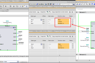
Refer to the below image, with highlighted inputs and outputs. This feature is available only in the following blocks – enhanced select (ESEL), totalizer (TOT), enhanced PID (PIDE), ramp/soak (RMPS), discrete 2-state device (D2SD) and discrete 3-state device (D3SD). Let us understand exactly how these features are implemented practically.

Studio 5000 Define Program or Operator Control in Functional Block Diagram

We will take the PID block that was discussed earlier for our reference. Suppose there is a chiller application, which has a compressor working on PID. When the compressor starts, some initial tuning must be done by the program, before any operator can make his inputs. This is for safety purposes and is required to be performed compulsorily. In that case, you can set the bit – ProgProgReq for that set time.

Due to this, the program will take control over PID, irrespective of whether the operator is doing something or not. Then, the bit can be reset and you can now set the bit ProgOperReq or any other bit for operator or program control afterwards. This provides greater flexibility to the programmer in controlling a sequence. Likewise, you can set and reset the other program/operator bits according to your requirements.

In this way, we saw how to define program or operator control in the functional block diagram of Studio 5000. In the next post, we will see how to manage sheets, tags and elements in this language of Studio 5000.

Read Next:

  • Network Switch Port Allocation Details
  • Failures in Industrial Automation Systems
  • HMI Screen Design for Water Treatment Plant
  • Motor Starter Logic using Siemens Tia Portal
  • FactoryTalk View Import and Export Tutorial
Don't Miss Our Updates
Be the first to get exclusive content straight to your email.
We promise not to spam you. You can unsubscribe at any time.
Invalid email address
You've successfully subscribed !

Continue Reading

How to Create New Project in Studio 5000?
Water Fountain Control Logic – PLC Exercises and Solutions
PLC Tag Naming Conventions
Retentive ON Delay Timer using PLC
Examples of SCADA and PLC Configuration Systems
PLC 1 Push Button to Turn ON or OFF 1 Output
Share This Article
Facebook Whatsapp Whatsapp LinkedIn Copy Link
Share
Leave a Comment

Leave a Reply Cancel reply

Your email address will not be published. Required fields are marked *

Stay Connected

128.3kFollowersLike
69.1kFollowersFollow
210kSubscribersSubscribe
38kFollowersFollow

Categories

Explore More

Structured Text in PLC: Parking Information Systems
How to Code a FIFO Queue in STL Language in Siemens PLC?
PLC Motor Control Ladder Logic Programming
Advanced Skills Required for a PLC Programmer to Get a Job
80+ PLC MCQ Questions
Alarm Acknowledge using PLC
How to use PLC with SQL Database? – Basics & Tutorials
Communicating Delta PLC Software to Simulator

Keep Learning

4-20mA Current Loop for Flow Transmitter and Control Valve Positioner

4–20 mA Process Control Loops

Automatic Liquid Mixing Application

PLC Program for Automatic Liquid Mixing Application

What is Ladder Diagram Programming ?

Instrumentation During the Detail Design Phase

Instrumentation Engineer Activities & Documents – Detail Design Phase

UDT in the PLC Programming

Implement UDT in PLC Programming: User-Defined Data Type

PLC Timer Programming Examples – TON, TOF, TP and TONR

PLC Ladder Logic for Motor Control

PLC Program for Motor Starter

Wiring in PLC System

Wiring in a PLC Control Panel

Learn More

Different Types of HVAC Applications

Different Types of HVAC Applications

COCO Simulator

COCO Simulator: Free Process Simulation Software

protective component or system

Safety Instrumented System Probability

Monsoon Protection for Field Instruments and Junction Boxes

Monsoon Protection for Field Instruments and Junction Boxes

Using Kirchhoff’s Voltage Law to find Current with Multiple Battery Sources

Kirchhoff’s Laws

Magnehelic Gauge Calibration

Magnehelic Gauge Calibration

MicroElectronics and Integrated Circuits Objective Questions and Answers

MicroElectronics and Integrated Circuits Objective Questions and Answers

Special Control Valves

Special Control Valves

Menu

  • About
  • Privacy Policy
  • Copyright

Quick Links

  • Learn PLC
  • Helping Hand
  • Part Time Job

YouTube Subscribe

Follow US
All rights reserved. Reproduction in whole or in part without written permission is prohibited.
Welcome Back!

Sign in to your account

Username or Email Address
Password

Lost your password?