Discover how to control an electric motor system for forward and reverse operations with repeat cycle programming in a PLC using CX-Programmer and CX-Designer
Introduction
This article discusses the PLC Electric Motor System Forward and Reverse program with Looping using CX-Programmer and Cx-Designer. This system can only be started if the Loop “Set Value” has been Set.
This system Runs automatically, the motor will Run in Forward mode during the “Set Value” time and will change to Reverse mode according to the “Set Value” time. This system will be Run again as many as Looping “Set Value” Looping.
Electric Motor Forward Reverse with Repeat Cycle
This PLC program only uses 2 buttons, the START_SYSTEM (0.00) button is used to turn ON the system, and the STOP_SYSTEM (0.01) button is used to turn OFF the system and Reset the data in memory word PV_LOOP (D0).
Before the system is Started, the “Set Value” in the memory word SV_LOOP (D1) must be Set. The memory word SV_LOOP (D1) is used as the “Set value” of the system Loop. For example, if the memory word SV_LOOP (D1) is Set to “3”, the system will be Run 3 times.
The memory word FORWARD_TIME (D10) is used as the “Set Value” of the timer TIMER_FORWARD (T0000) and the memory word REVERSE_TIME (D11) is used as the “Set Value” of the timer TIMER_REVERSE (T0001).
When the START_SYSTEM (0.00) button is pressed, the output FORWARD (100.00) will be ON. The FORWARD (100.00) output will be OFF when timer TIMER_FORWARD (T0000) has reached the “Set Value”.
When the TIMER_FORWARD (T0000) timer has finished counting, the REVERSE (100.01) output will be ON. The REVERSE (100.01) output will be OFF when timer TIMER_REVERSE (T0001) has reached the “Set Value”.
When the timer TIMER_REVERSE (T0001) has finished counting, the value in memory word PV_LOOP (D0) will increase (+1).
The sequence of this program will be executed again according to the “Set Value” memory word SV_LOOP (D1). When the program has been executed according to the “Set Value” memory word SV_LOOP (D1), the system will be OFF.
Inputs and Outputs
| Comment | Input (I) | Output(Q) | Memory Word | Memory Bits | Timer |
| START_SYSTEM | 0.00 | ||||
| STOP_SYSTEM | 0.01 | ||||
| FORWARD | 100.00 | ||||
| REVERSE | 100.01 | ||||
| TIMER_FORWARD | T0000 | ||||
| TIMER_REVERSE | T0001 | ||||
| SYSTEM_ON | W0.00 | ||||
| LOOP_CUTOFF | W0.01 | ||||
| PV_LOOP | D0 | ||||
| SV_LOOP | D1 | ||||
| FORWARD_TIME | D10 | ||||
| REVERSE_TIME | D11 |
Omron PLC Programming
RUNG 0
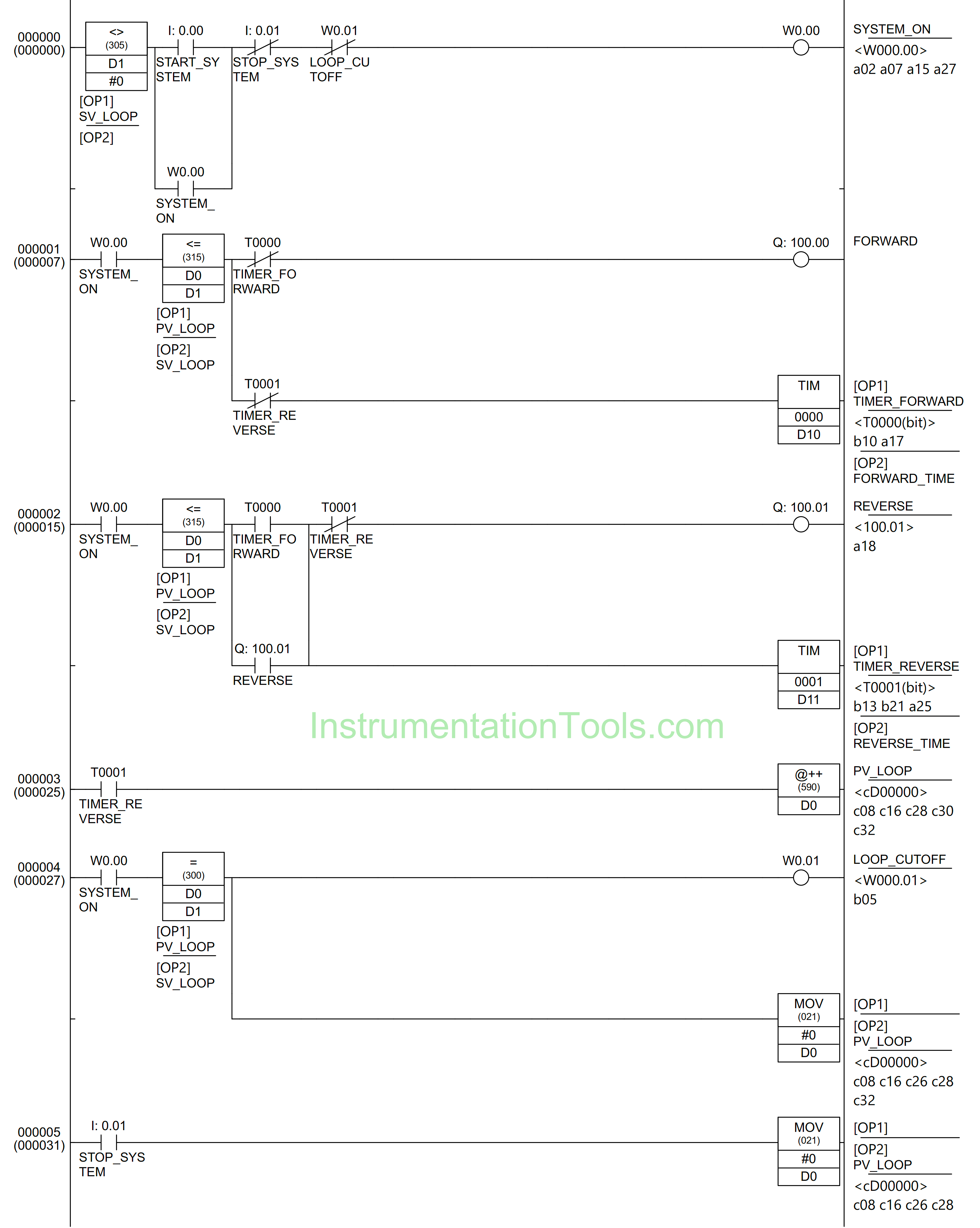
In this Rung, the memory bit SYSTEM_ON (W0.00) will be ON when the memory word SV_LOOP (D1) has a value Not Equal to zero “0” and the START_SYSTEM (0.00) button is Pressed. Because it uses Latching, the memory bit SYSTEM_ON (W0.00) remains in the HIGH state even though the START_SYSTEM (0.00) button has been Released.
The memory bit SYSTEM_ON (W0.00) will be in the LOW state if the STOP_SYSTEM (0.01) button is Pressed or the NC contact of memory bit LOOP_CUTOFF (W0.01) is in the HIGH state.
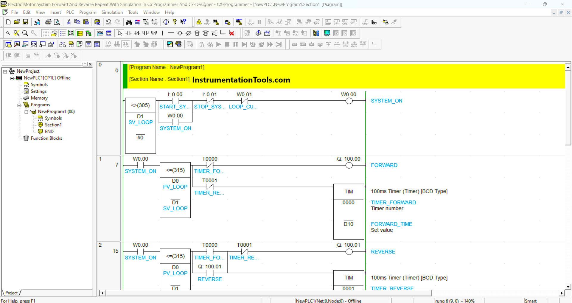
RUNG 1
In this Rung, the FORWARD (100.00) output will be ON if the NO contact of memory bit SYSTEM_ON (W0) is in a HIGH state and the value of memory word PV_LOOP (D0) is Less Than Or Equal to SV_LOOP (D1).
The timer TIMER_FORWARD (T0000) will count up to “Set value”.
The FORWARD (100.00) output will be OFF when the NC contact of timer TIMER_FORWARD (T0000) or TIMER_REVERSE (T0001) is in a HIGH state or if the value of memory word PV_LOOP (D0) is Greater Than SV_LOOP (D1).
RUNG 2
In this Rung, the REVERSE (100.01) output will be ON if the NO contact of memory bit SYSTEM_ON (W0.00) and the timer TIMER_FORWARD (T0000) in HIGH state and the value of memory word PV_LOOP (D0) is Less Than Or Equal to SV_LOOP (D1).
Because it uses Latching, the REVERSE (100.01) output will be ON even though the timer TIMER_FORWARD (T0000) is in the LOW state.
The timer TIMER_REVERSE (T0001) will count up to “Set value”.
The REVERSE (100.01) output will be OFF when the NC contact of timer TIMER_REVERSE (T0001) in a HIGH state or if the value of memory word PV_LOOP (D0) is Greater Than SV_LOOP (D1).
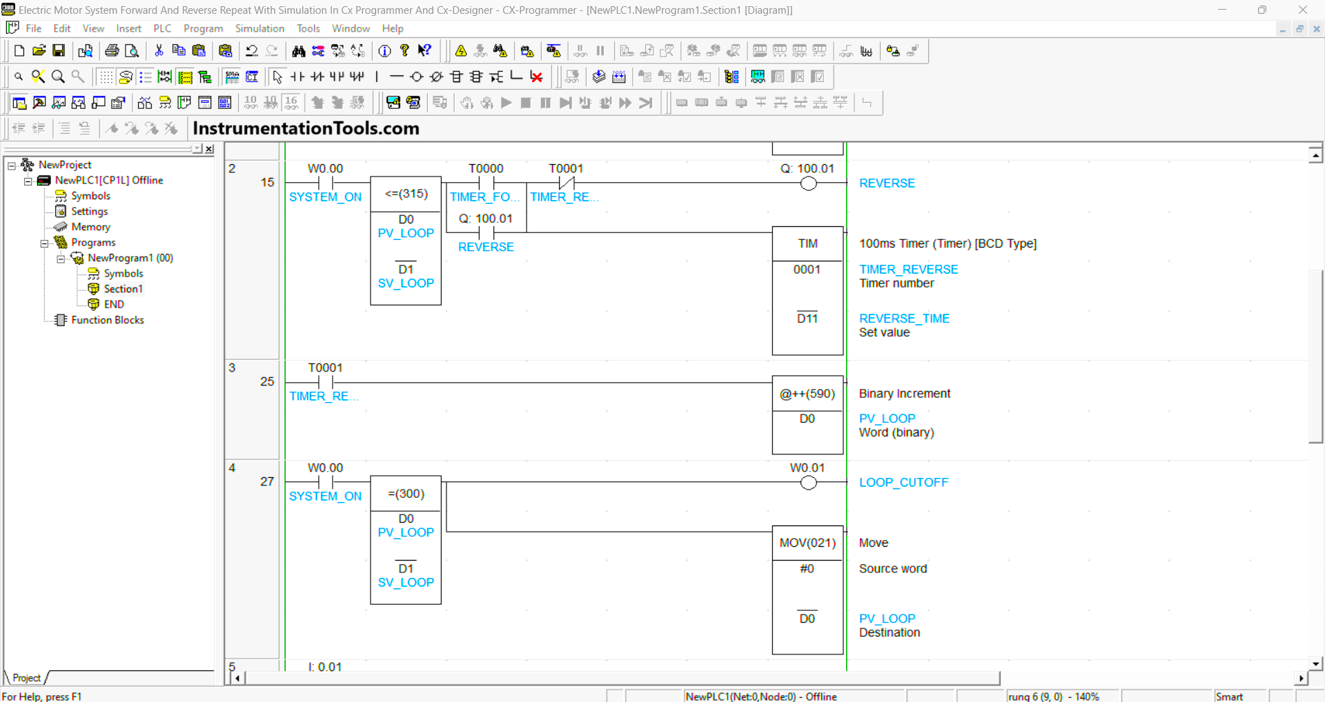
RUNG 3
If the NO contact of timer TIMER_FORWARD(T0000) is in a HIGH state, then the value in memory word PV_LOOP (D0) will increase (+1).
RUNG 4
When the memory bit SYSTEM_ON (W0.00) in the HIGH state and the value in memory word PV_LOOP (D0) is equal to SV_LOOP (D1), then the memory bit LOOP_CUTOFF (W0.01) will become HIGH state and the value in memory word PV_LOOP (D0) changed to zero “0” due to the MOV(021) instruction.
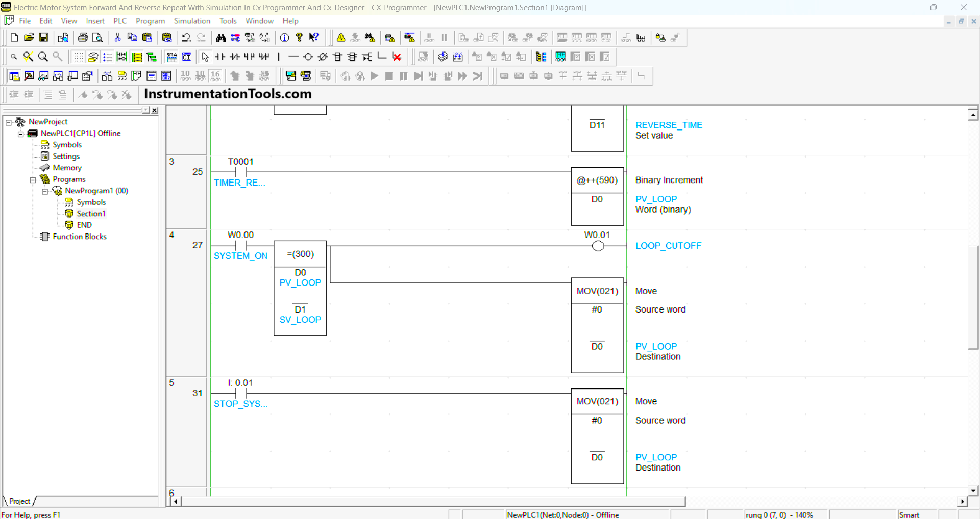
RUNG 5
When the STOP_SYSTEM (0.01) button is Pressed, the value in the memory word PV_LOOP (D0) changes to zero “0” because of the MOV(021) instruction.
Simulation
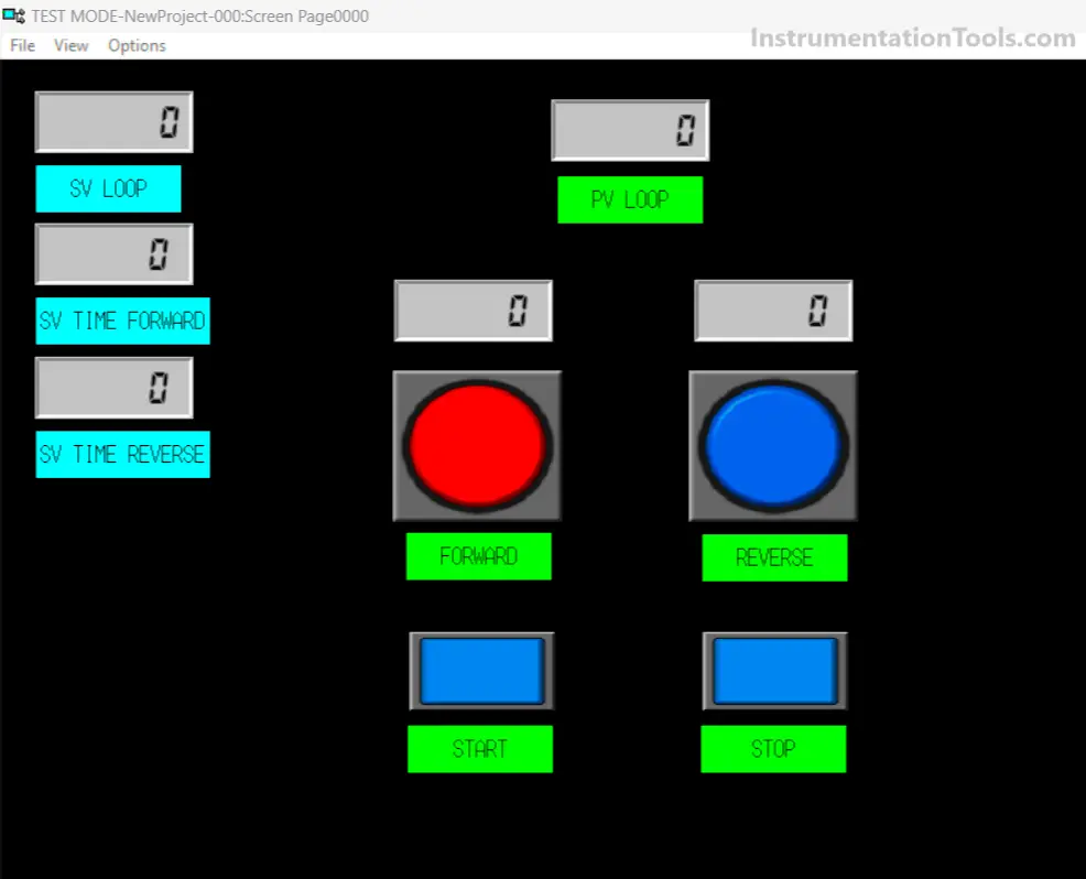
The simulation image above is a situation when the “Set value” of all parameters has not been Set and the system has not been Started.
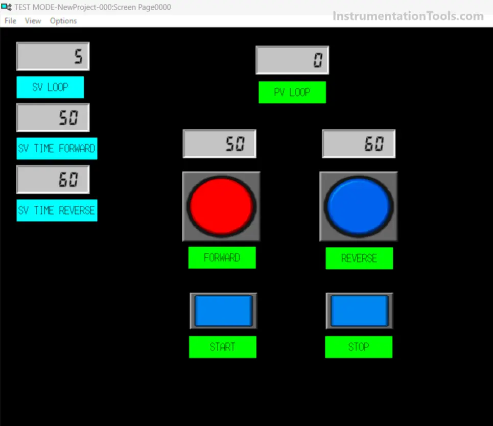
The simulation image above is the situation when the “Set value” of all parameters has been set but the system has not been Started.
You can see that the SV_LOOP parameter is Set to “5” times, SV TIME FORWARD is Set to “5” seconds and SV TIME REVERSE is Set to “6” seconds.
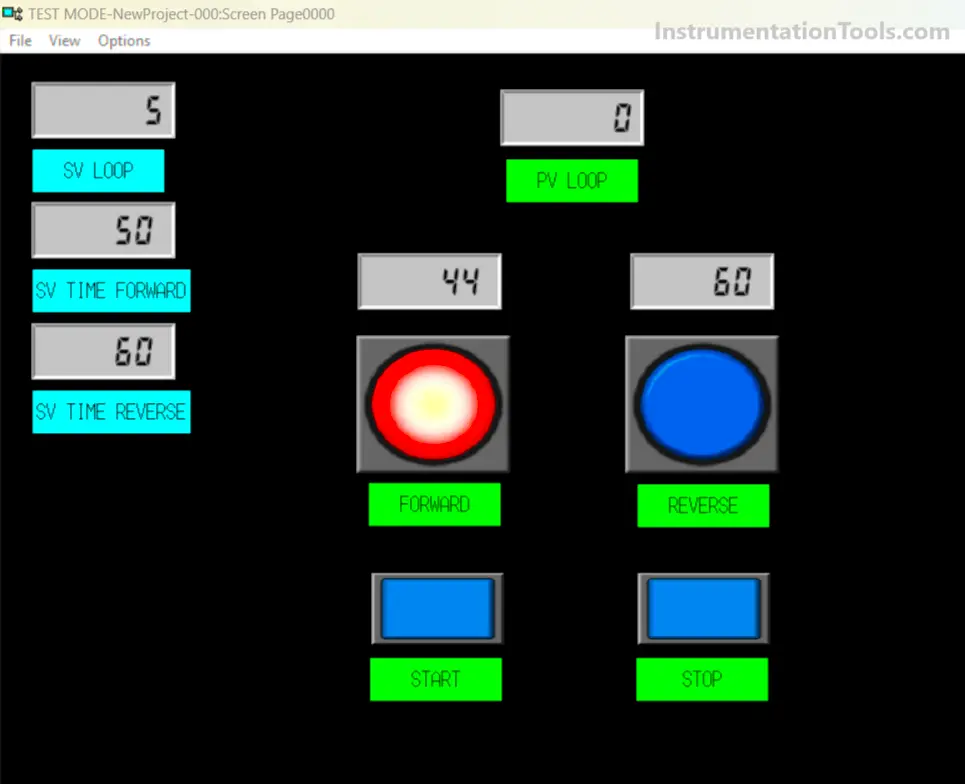
In the simulation image above you can see that the FORWARD light is ON and the timer is Starting to count.
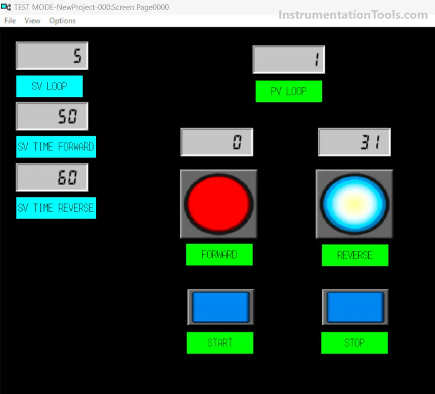
In the simulation image above, you can see that the REVERSE light is ON and the PV LOOP value is “1”, meaning that the Looping has been carried out 1 time.
Read Next:
- Sanitizer Complex Ladder Logic PLC Example
- Door Locking System PLC Application Example
- CX-Programmer Products Sorting & Counting
- Real-Time Clock in Omron CX Programmer
- PLC Program for Ceramic Burning Oven


Is there any video of the execution of this program