The Doll Claw Program has 7 main buttons, the START button (0.00) is used to Turn ON the system, the STOP button (0.01) is used to Reset the “Doll Claw” to the initial position, the UP button (0.02) is used to move the “Doll Claw” towards Up.
The DOWN (0.03) button is used to move the “Doll Claw” Downwards, the LEFT (0.04) button is used to move the “Doll Claw” to the Left, the RIGHT button (0.05) is used to move the “Doll Claw” to the Right, and CLAW (0.08) is used to turn ON Out_CLAW (100.04).
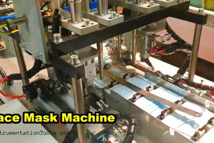
Doll Claw Machine
When the system is not Running, the Memory Word SEQUENCE (D0) will have a value of zero ‘0’ and the “Doll Claw” can only be moved Up and Down. The starting position of “Doll Claw” is on the Left.
When the START (0.00) button is pressed, the Memory Word SEQUENCE (D0) will have the value ‘1’. In this situation, the “Doll Claw” can be moved Up, Down, Left, And Right. When the CLAW (0.08) button is Pressed, IR_CLAW_CLOSE (W0.09) will be ON and OUT_CLAW (100.04) will be Active.
When the CLAW (0.08) button is Pressed, TIMER_GAME_END (T0000) will start counting up to ‘5’ seconds. TIMER_GAME_END (T0000) which is ON changes the value in Memory Word SEQUENCE (D0) to ‘2’, then the “Doll Claw” will move Up and will Stop when Sensor LS2 (0.06) becomes ON. Next, the “Doll Claw” moves to the Left towards the starting position and will Stop when the LS1 (0.07) sensor becomes ON.
Because “Doll Claw” has returned to its initial position, Out_CLAW (100.04) will be OFF and the Memory Word SEQUENCE (D0) will have a zero value of ‘0’.
IO Details
Addressing Input, Output, TIM, Bit Memory, and Word Memory details are as follows.
| Comment | Input (I) | Output(Q) | Memory Word | Memory Bits | Timer |
| START | 0.00 | ||||
| STOP | 0.01 | ||||
| UP | 0.02 | ||||
| DOWN | 0.03 | ||||
| LEFT | 0.04 | ||||
| RIGHT | 0.05 | ||||
| LS1 | 0.06 | ||||
| LS2 | 0.07 | ||||
| CLAW | 0.08 | ||||
| OUT_UP | 100.00 | ||||
| OUT_DOWN | 100.01 | ||||
| OUT_LEFTR | 100.02 | ||||
| OUT_RIGHT | 100.03 | ||||
| OUT_CLAW | 100.04 | ||||
| IR_UP0 | W0.00 | ||||
| IR_DOWN0 | W0.01 | ||||
| IR_UP1 | W0.02 | ||||
| IR_DOWN1 | W0.03 | ||||
| IR_LEFT1 | W0.04 | ||||
| IR_RIGHT1 | W0.05 | ||||
| IR_TIMER | W0.06 | ||||
| IR_UP2 | W0.07 | ||||
| IR_LEFT2 | W0.08 | ||||
| IR_CLAW_CLOSE | W0.09 | ||||
| IR_CLAW_OPEN | W0.10 | ||||
| SEQUENCE | D0 | ||||
| TIMER_GAME_END | T0000 |
PLC Programming
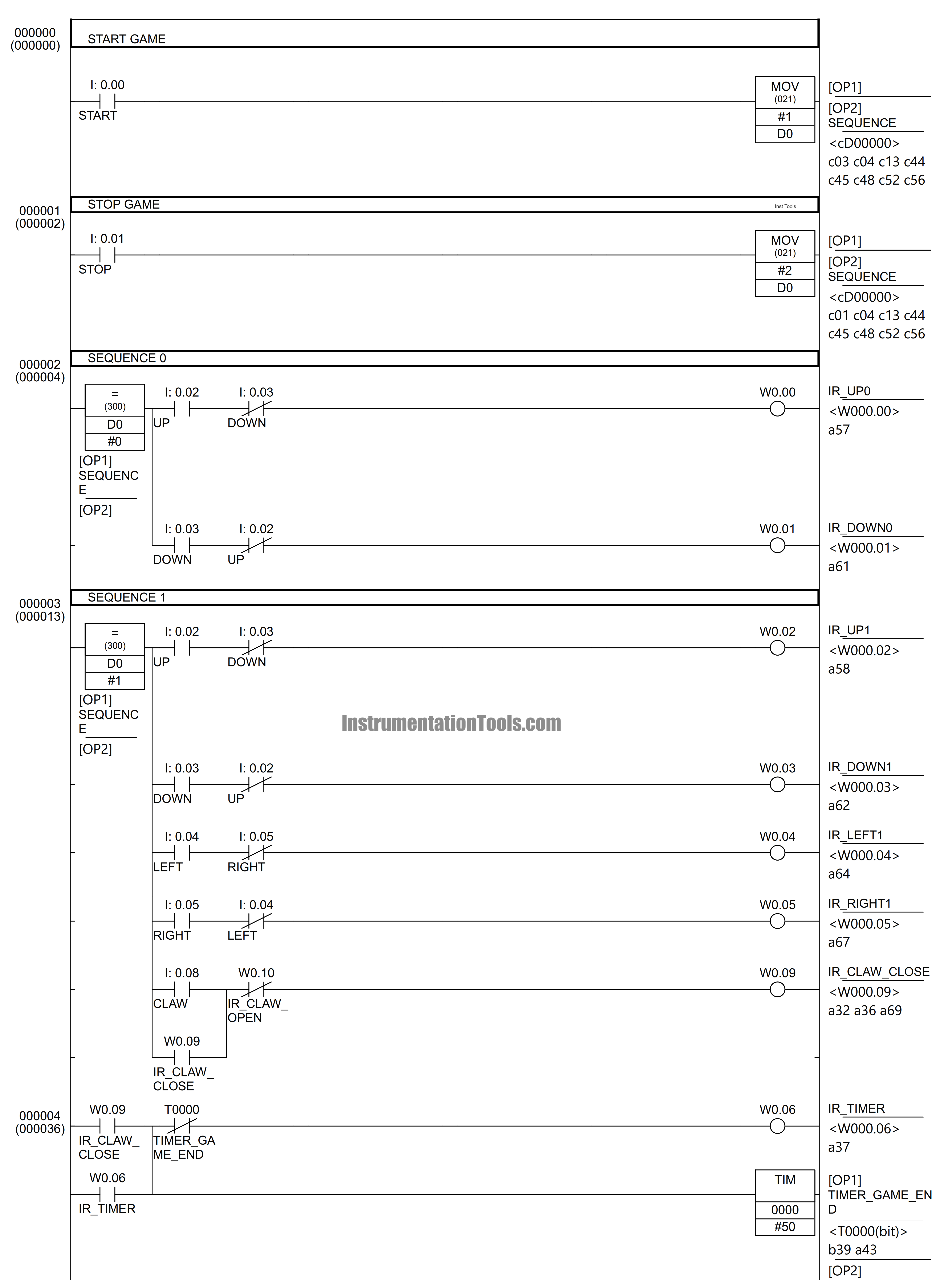
Rung 0
When the START (0.00) button is pressed, the MOV Instruction will move the value ‘1’ to the Memory Word SEQUENCE (D0), so that SEQUENCE (D0) becomes the value ‘1’.
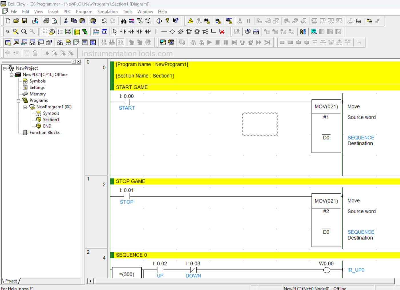
RUNG 1
When the STOP (0.01) button is pressed, the MOV Instruction will move the value ‘2’ to the Memory Word SEQUENCE (D0), so that SEQUENCE (D0) becomes the value ‘2’.
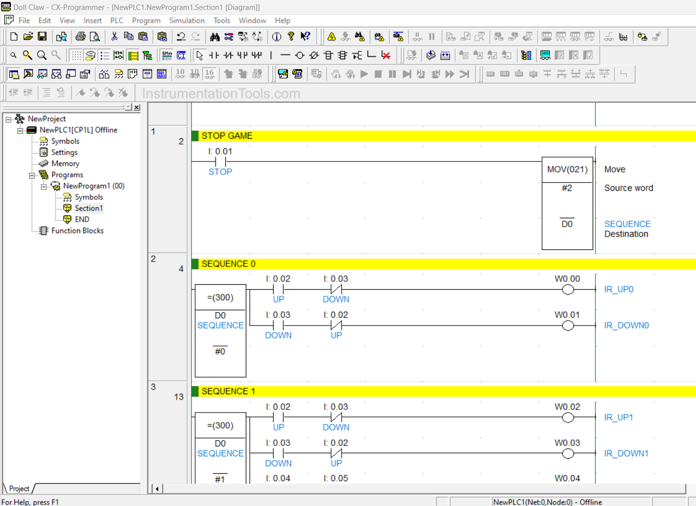
RUNG 2
In this Rung, when the Memory Word SEQUENCE (D0) is equal to ‘0’ then the system can be Run. When the UP (0.02) button is pressed, the Bit Memory IR_UP0 (W0.00) will be ON and when the DOWN (0.03) button is pressed, the Bit Memory IR_DOWN0 (W0.01) will be ON.
Due to the interlock of the UP (0.02) button and DOWN (0.03) button, the Bit Memory IR_UP0 (W0.00) and IR_DOWN0 (W0.01) cannot be ON at the same time.
RUNG 3
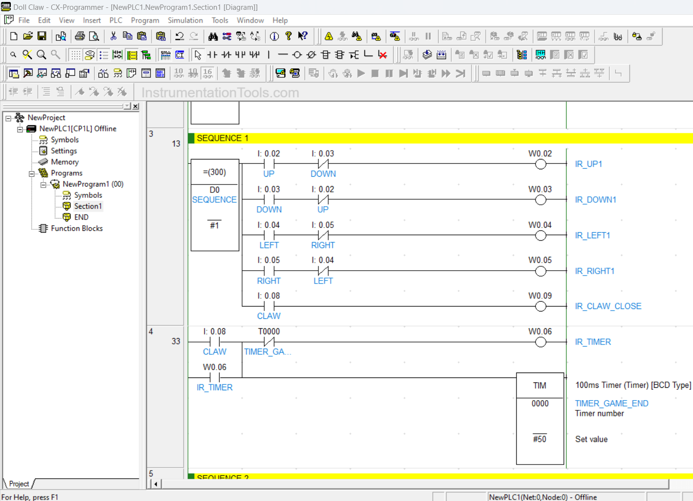
In this Rung, the system can only be Run when the Memory Word SEQUENCE (D0) has a value equal to ‘1’.
When the UP (0.02) button is pressed then the Bit Memory IR_UP1 (W0.02) will be ON and when the DOWN (0.03) button is pressed then the Bit Memory IR_DOWN1 (W0.03) will be ON.
When the LEFT (0.04) button is pressed then the Bit Memory IR_LEFT1 (W0.04) will be ON and when the RIGHT (0.05) button is pressed then the Bit Memory IR_RIGHT1(W0.05) will be ON. IR_CLAW_CLOSE (W0.09) will be ON when the CLAW (0.08) button is Pressed.
RUNG 4
In this Rung, when the CLAW (0.08) button is pressed, the Bit Memory IR_TIMER (W0.06) will be ON, and TIMER_GAME_END (T0000) will start counting up to ‘5’ seconds. Once TIMER_GAME_END (T0000) reaches ‘Set value’ then the Bit Memory IR_TIMER (W0.06) becomes OFF.
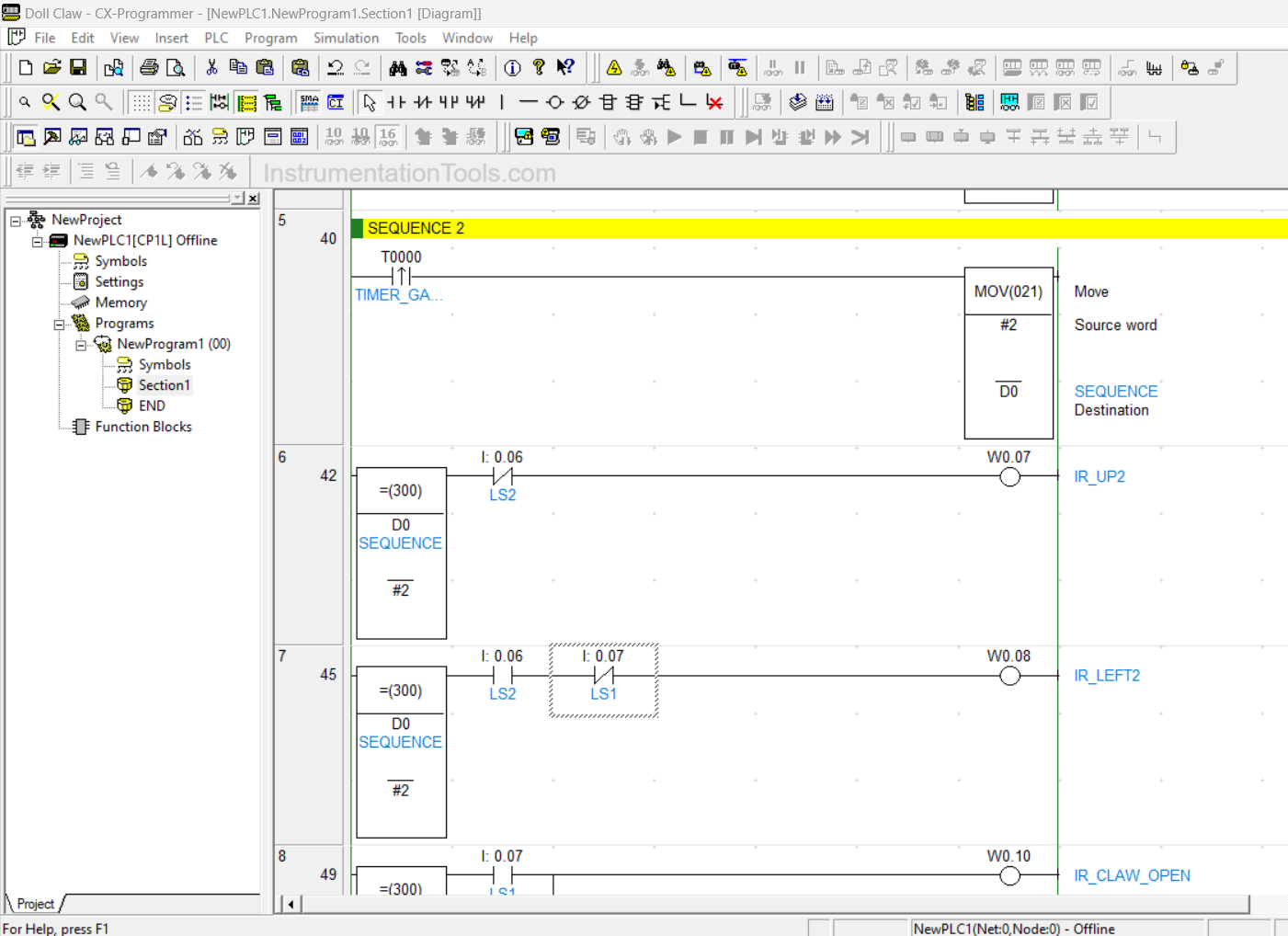
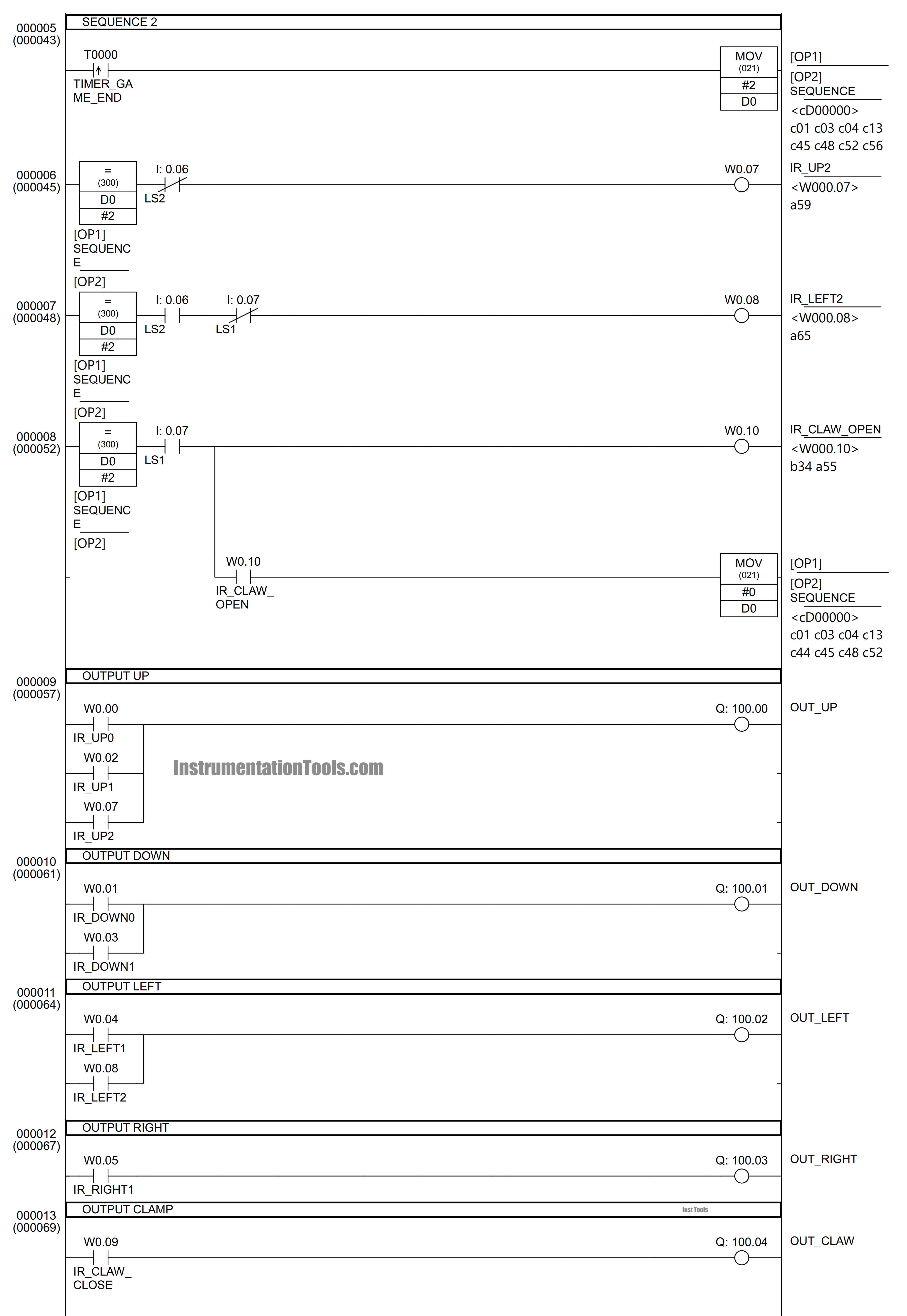
RUNG 5
When the NO (Normally Open) TIMER_GAME_END (T0000) contact is ON, the MOV Instruction will move the value ‘2’ to the Memory Word SEQUENCE (D0), so that SEQUENCE (D0) changes to the value ‘2’.
RUNG 6
When the Memory Word SEQUENCE (D0) is equal to ‘2’ then the Memory Bit IR_UP2(W0.07) will be ON. Bit Memory IR_UP2 (W0.07) will be OFF when the NC (Normally Close) contact of Sensor LS2 (0.06) changes to the HIGH state.
RUNG 7
When the Memory Word SEQUENCE (D0) is equal to ‘2’ and contact NO (Normally Open) Sensor LS2 (0.06) has been in a HIGH state then the Memory Bit IR_LEFT2 (W0.08) will be ON. Memory Bit IR_ LEFT2 (W0.08) will be OFF when NC (Normally Close) contact Sensor LS1 (0.07) changed to HIGH state.
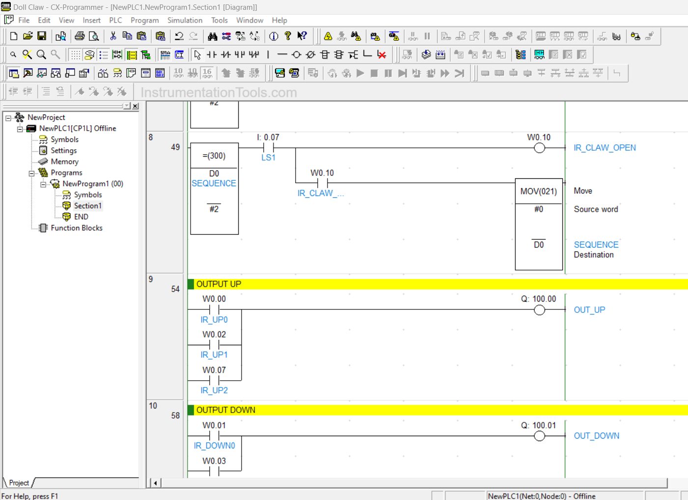
RUNG 8
When the Memory Word SEQUENCE (D0) is equal to ‘2’ and contact NO (Normally Open) Sensor LS1 (0.07) in the HIGH state then the Memory Bit IR_CLAW_OPEN (W0.10) will be ON and change the Memory Word SEQUENCE (D0) to ‘0’ using the MOV instruction.
RUNG 9
Coil Output OUT_UP (100.00) will be ON when contact NO (Normally Open) of IR_UP0 (W0.00) or IR_UP1 (W0.02) or IR_UP2 (W0.07) in HIGH state.
RUNG 10
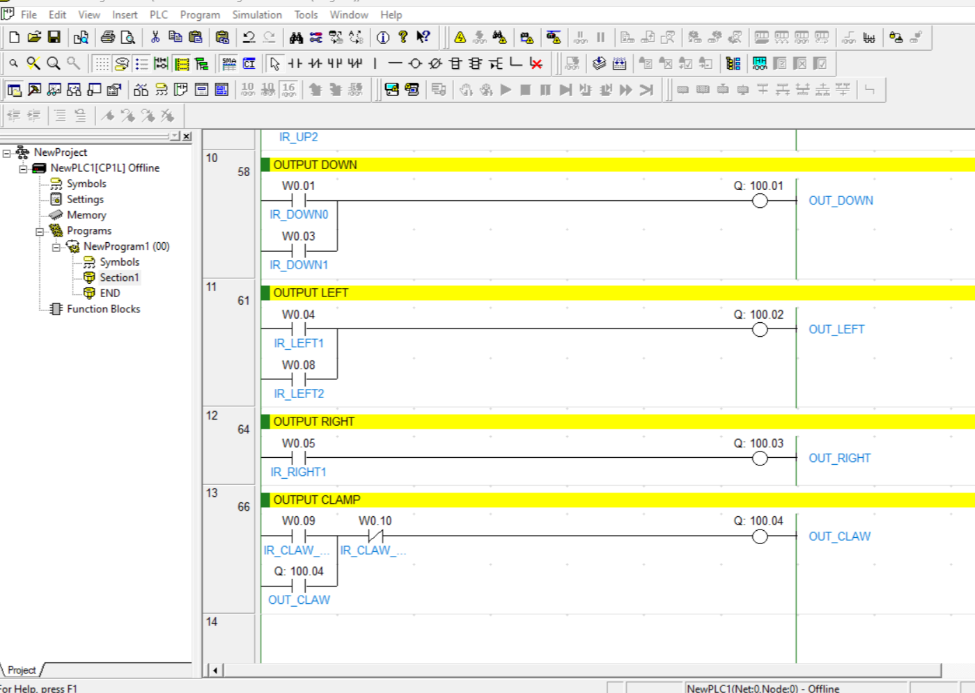
Coil Output OUT_DOWN (100.01) will be ON when contact NO (Normally Open) of IR_DOWN0 (W0.01) or IR_DOWN1 (W0.03) in the HIGH state.
RUNG 11
Coil Output OUT_LEFT (100.02) will be ON when contact NO (Normally Open) of IR_LEFT1 (W0.04) or IR_LEFT2 (W0.08) in the HIGH state.
RUNG 12
Coil Output OUT_RIGHT (100.03) will be ON when the NO (Normally Open) contact of IR_RIGHT1 (W0.05) is HIGH.
RUNG 13
Coil Output OUT_CLAW (100.04) will be ON when contact NO (Normally Open) IR_CLAW_CLOSE (W0.09) is in a HIGH state. Because using Latching Coil Output OUT_CLAW (100.04) will remain ON even though Contact NO (Normally Open) IR_CLAW_CLOSE (W0.09) has changed to LOW state. Coil Output OUT_CLAW (100.04) will be OFF when NC (Normally Close) contact IR_CLAW_OPEN (W0.10) turns into a HIGH state.
If you liked this article, please subscribe to our YouTube Channel for PLC and SCADA video tutorials.
You can also follow us on Facebook and Twitter to receive daily updates.
Read Next:
- Real-Time Clock in Omron PLC?
- Light ON OFF Control using PLC Programming
- Water Pump PLC Program using CX-Programmer
- Motion Detection based Street Light PLC Logic
- Car Parking System with Calculations in PLC Logic