In this article, you will learn the glass cutting and polishing machine PLC programming and automation solution.
Note: This example PLC program is for education and for practicing ladder logic.
Glass Cutting and Polishing Machine
Problem Statement:
Design a PLC ladder logic for the following application.
We are using one Push Button to control Glass products’ Cutting and Polishing.
A Machine is used to cut and polish glasses.
Push Button by pressing and releasing is used to carry on the cutting the glass process which takes 10 seconds.
Then again on pressing and releasing the same push button for the second time, we will be able to polish the glass which takes place for 15 seconds.
PLC Automation Solution
Instrumentation Tools provides PLC automation solutions and programming videos with example problems.
This PLC programming video explains the glass products cutting and polishing logic.
Inputs and Outputs
Digital Inputs:
Push Button: I0.0
Digital Outputs:
Cutting: Q0.0
Polishing: Q0.1
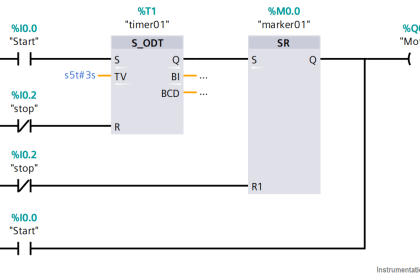
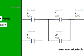
PLC Ladder Logic
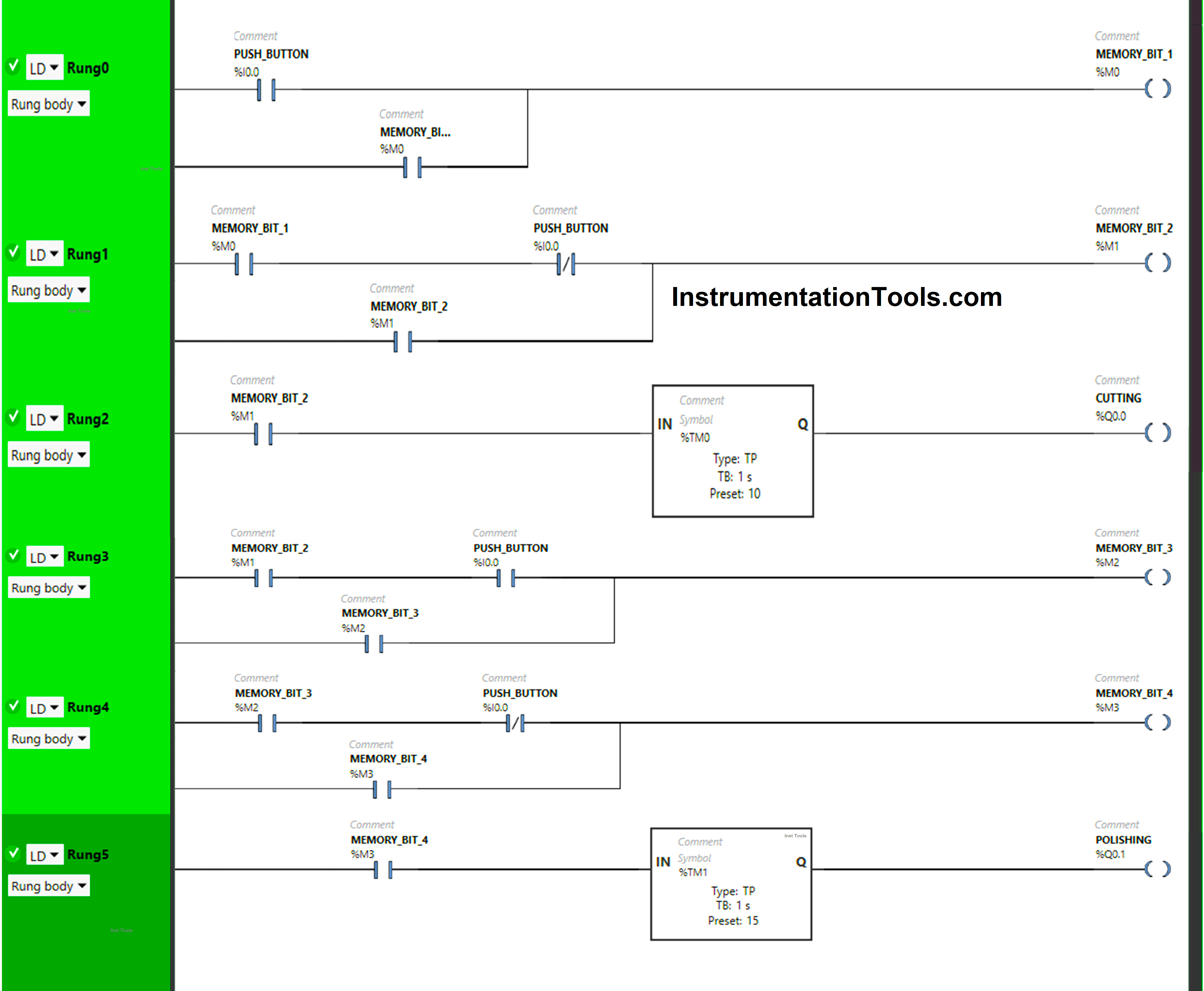
Program Explanation
We have used Normally Open Contacts for Push Button(I0.0) and Memory Bits.
We have used Normally Closed Contacts for Push Button (I0.0).
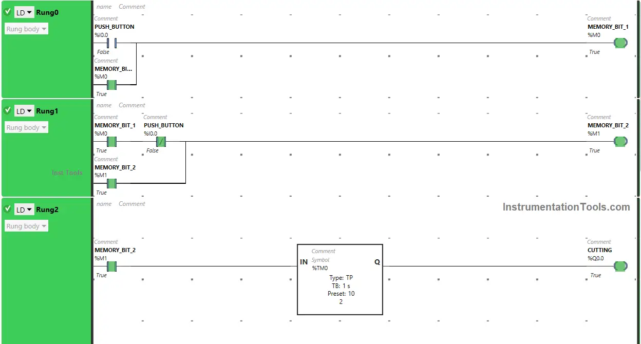
In Rung 0:
- Normally Open Contact is used for Push Button (I0.0) to Turn ON Memory Bit 1 (M0).
- Memory Bit 1 (M0) is latched so that when the Push Button (I0.0) turns OFF, Memory Bit 1 (M0) still remains ON.
In Rung 1:
- Normally Open Contact is used for Memory Bit 1 (M0) to Turn ON Memory Bit 2 (M1).
- Normally Closed Contact is used for Push Button (I0.0) to Turn ON Memory Bit 2 (M1).
- Memory Bit 2 (M1) is latched so that when Memory Bit 1 (M0) turns OFF, Memory Bit 2 (M1) still remains ON.
In Rung 2:
- Normally Open Contact is used for Memory Bit 2 (M1) to Turn ON the output Cutting (Q0.0).
- Timer Function Block type TP is used to turn ON the output Cutting (Q0.0) for a limited time.
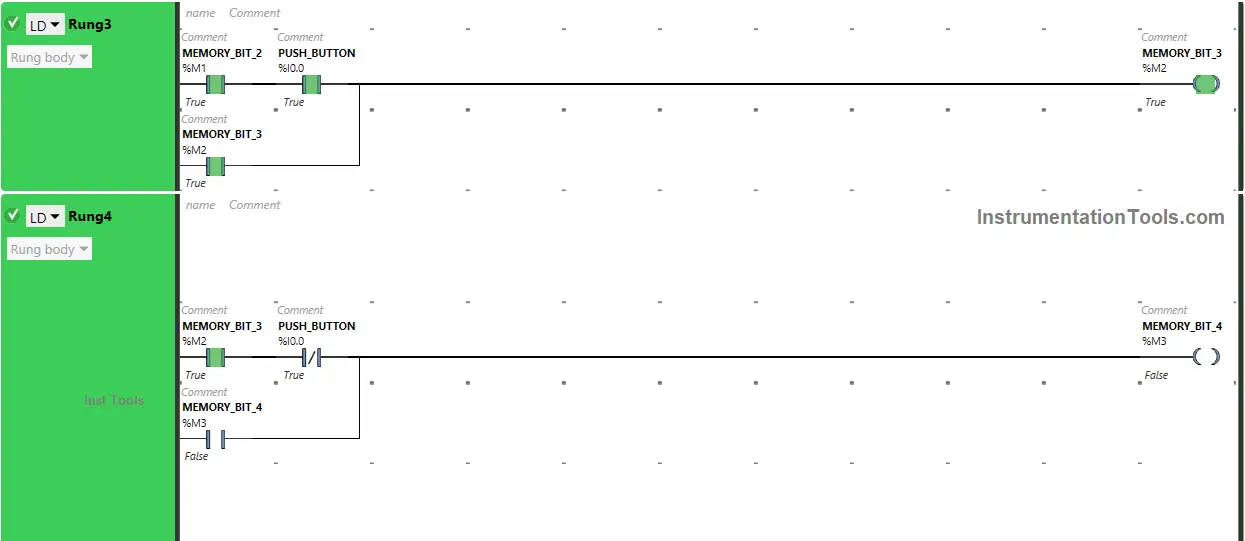
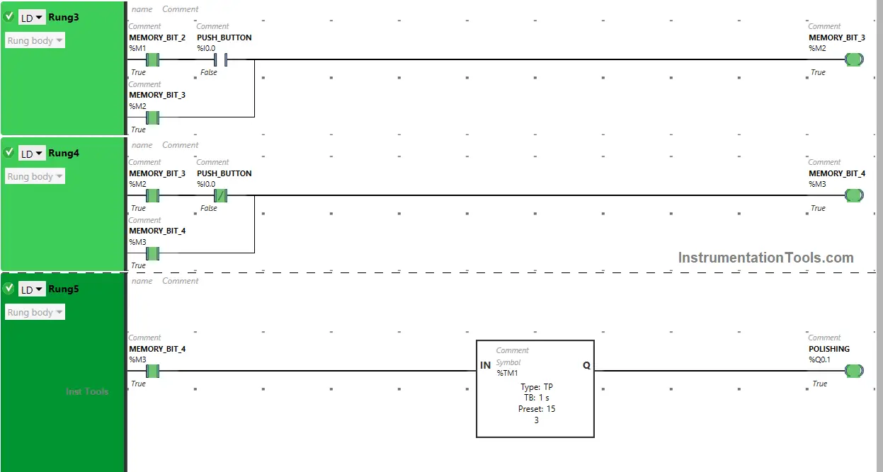
In Rung 3:
- Normally Open Contacts are used for Push Button (I0.0) and Memory Bit 2 (M1) to turn ON Memory Bit 3 (M2).
- Memory Bit 3 (M2) is latched so that when the Push Button (I0.0) or Memory Bit 2 (M1) turns OFF, Memory Bit 3 (M2) still remains ON.
In Rung 4:
- Normally Open Contact is used for Memory Bit 3 (M2) to Turn ON Memory Bit 4 (M3).
- Normally Closed Contact is used for Push Button (I0.0) to Turn ON Memory Bit 4 (M3).
- Memory Bit 4 (M3) is latched so that when Memory Bit 3 (M2) turns OFF, Memory Bit 4 (M3) still remains ON.
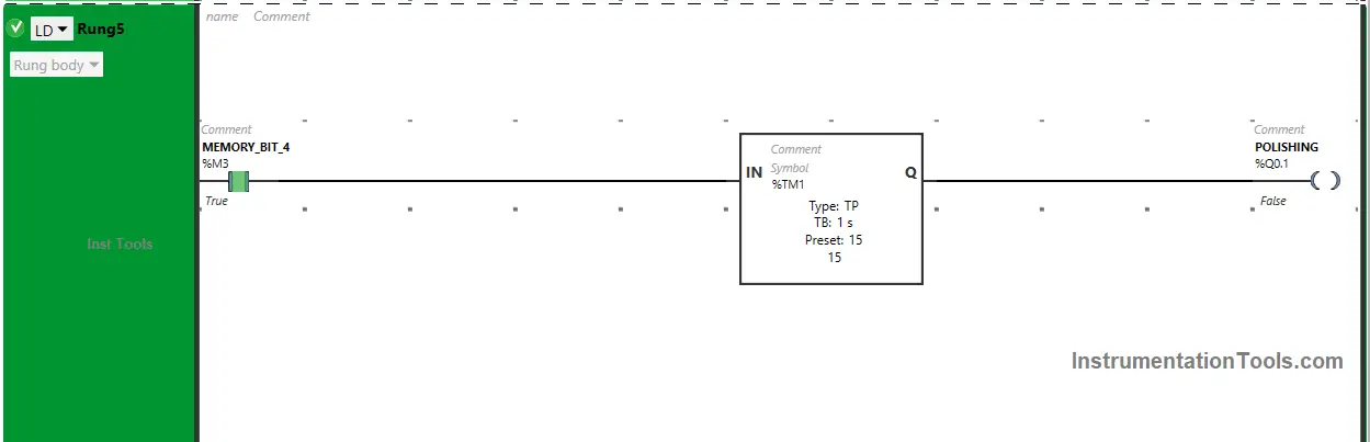
In Rung 5:
- Normally Open Contact is used for Memory Bit 4 (M3) to Turn ON the output Polishing (Q0.1).
- Timer Function Block type TP is used to turn ON the output Polishing (Q0.1) for a limited time.
Simulation Results
We will simulate the PLC program and analyze the results. Please note that we may show the partial logic code instead of the complete program.
When the Push Button is pressed and released the first time
When Push Button (I0.0) is pressed the first time, Memory Bit 1 (M0) turns ON and stores the data that Push Button (I0.0) is pressed the first time as Memory bits store the data.
Memory Bit 1 (M0) is latched so that when the Push Button (I0.0) is released, Memory Bit 1 (M0) still remains ON.
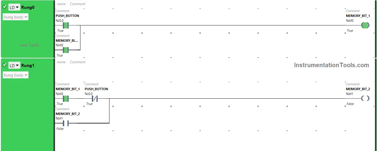
When Push Button (I0.0) is released first time in Rung0, Normally Closed Contact used for Push Button (I0.0) in Rung1 will be in a false state and will pass the signal to turn ON Memory Bit 2 (M1).
When Memory Bit 1 (M0) turns ON in Rung0, Normally Open Contact used for Memory Bit 1 (M0) in Rung1 will be in True State and will pass the signal to turn ON Memory Bit 2 (M1), and Memory Bit 2 (M1) will turn ON in Rung1.
Memory Bit 2 (M1) will store the data that Push Button (I0.0) is released the first time. Memory Bit 2 (M1) is latched so that when Memory Bit 1 (M0) turns OFF, Memory Bit 2 (M1) still remains ON.
When Memory Bit 2 (M1) turns ON in Rung1, Normally Open Contact used for Memory Bit 2 (M1) in Rung2 will be in True state and pass the signal to turn ON the output Cutting (Q0.0) and the output Cutting (Q0.0) will turn ON (Machine starts cutting glass).
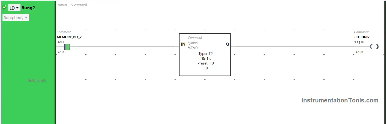
The output Cutting (Q0.0) will turn OFF after some time as Timer Function Block type TP is used to turn ON the output Cutting (Q0.0) for a limited time.
The time is set to 10 seconds. After 10 seconds, the output Cutting (Q0.0) will turn OFF.
When the Push Button is pressed and released the Second time
When the Push Button (I0.0) is pressed the Second time, Memory Bit 3 (M2) turns ON as Normally Open Contact used for Push Button (I0.0) will be in True state and will pass the signal to turn ON Memory Bit 3 (M2).
When Memory Bit 2 (M1) turns ON in Rung1, Normally Open Contact used for Memory Bit 2 (M1) in Rung3 will be in a True state and will also pass the signal to turn ON Memory Bit 3 (M2), and Memory Bit 3 (M2) will turn ON.
Memory Bit 3 (M2) stores the data that Push Button (I0.0) is pressed the Second time as Memory bits stores the data. Memory Bit 3 (M2) is latched so that when the Push Button (I0.0) is released, Memory Bit 3 (M2) still remains ON.
When the Push Button (I0.0) is released the Second time, the Normally Closed Contact used for Push Button (I0.0) in Rung4 will be in a false state and will pass the signal to turn ON Memory Bit 4 (M3).
Also, When Memory Bit 3 (M2) turns ON in Rung3, Normally Open Contact used for Memory Bit 3 (M2) in Rung4 will be in True State and will pass the signal to turn ON Memory Bit 4 (M3), and Memory Bit 4 (M3) will turn ON in Rung4.
Memory Bit 4 (M3) will store the data that Push Button (I0.0) is released Second time. Memory Bit 4 (M3) is latched so that when Memory Bit 3 (M2) turns OFF, Memory Bit 4 (M3) still remains ON.
When Memory Bit 4 (M3) turns ON in Rung4, Normally Open Contact used for Memory Bit 4 (M3) in Rung4 will be in True state and passes the signal to turn ON the output Polishing (Q0.1) and the output Polishing (Q0.1) will turn ON ( Machine starts polishing glass).
The output Polishing (Q0.1) will turn OFF after some time as the Timer Function Block type TP is used to turn ON the output Polishing (Q0.1) for a limited time. The time is set to 15 seconds. After 15 seconds, the output Polishing (Q0.1) will turn OFF.
If you liked this article, please subscribe to our YouTube Channel for PLC and SCADA video tutorials.
You can also follow us on Facebook and Twitter to receive daily updates.
Read Next:
- How to use a Simulator in Siemens PLC Software?
- Automatic Car Washing using PLC Programming
- PLC Programming for Defective Parts Sorting
- PLC Example on Manufacturing Line Assembly
- Three Motors control PLC Programming Logic