Inst ToolsInst ToolsInst Tools
  • Courses
  • Automation
    • PLC
    • Control System
    • Safety System
    • Communication
    • Fire & Gas System
  • Instrumentation
    • Design
    • Pressure
    • Temperature
    • Flow
    • Level
    • Vibration
    • Analyzer
    • Control Valve
    • Switch
    • Calibration
    • Erection & Commissioning
  • Interview
    • Instrumentation
    • Electrical
    • Electronics
    • Practical
  • Q&A
    • Instrumentation
    • Control System
    • Electrical
    • Electronics
    • Analog Electronics
    • Digital Electronics
    • Power Electronics
    • Microprocessor
  • Request
Search
  • Books
  • Software
  • Projects
  • Process
  • Tools
  • Basics
  • Formula
  • Power Plant
  • Root Cause Analysis
  • Electrical Basics
  • Animation
  • Standards
  • 4-20 mA Course
  • Siemens PLC Course
Reading: PLC Example on Switch Program with Timers
Share
Font ResizerAa
Inst ToolsInst Tools
Font ResizerAa
  • Courses
  • Design
  • PLC
  • Interview
  • Control System
Search
  • Courses
  • Automation
    • PLC
    • Control System
    • Safety System
    • Communication
    • Fire & Gas System
  • Instrumentation
    • Design
    • Pressure
    • Temperature
    • Flow
    • Level
    • Vibration
    • Analyzer
    • Control Valve
    • Switch
    • Calibration
    • Erection & Commissioning
  • Interview
    • Instrumentation
    • Electrical
    • Electronics
    • Practical
  • Q&A
    • Instrumentation
    • Control System
    • Electrical
    • Electronics
    • Analog Electronics
    • Digital Electronics
    • Power Electronics
    • Microprocessor
  • Request
Follow US
All rights reserved. Reproduction in whole or in part without written permission is prohibited.
Inst Tools > Blog > PLC Tutorials > PLC Example on Switch Program with Timers

PLC Example on Switch Program with Timers

The PLC example on switch program to control the output 1 and output 2 status based on the timers value.

Last updated: May 6, 2024 10:37 am
Editorial Staff
PLC Tutorials
No Comments
Share
3 Min Read
SHARE

The PLC example on switch program to control the output 1 and output 2 status based on the timers value.

Contents
PLC Example on Switch ProgramBest Industrial Automation VideosInputs & OutputsLadder LogicProgram DescriptionSimulation ResultWhen Switch (I0.0) is turned ONWhen Switch (I0.0) is turned OFF

Note: These PLC programs are designed for engineering students and beginners to understand the basics.

PLC Example on Switch Program

Problem Statement:

Design a PLC ladder logic for the following application.

We are using one switch to control 2 outputs.

When the Switch is turned ON, Output 1 and Output 2 will be ON.

When the Switch is turned OFF, Output 1 will be OFF after 10 seconds and Output 2 will be OFF after 15 seconds.

Best Industrial Automation Videos

Instrumentation Tools provides you the best industrial automation videos for training the students all-over the world.

PLC Ladder Logic Examples - Switch Program

Inputs & Outputs

Digital Inputs:

Switch: I0.0

Digital Outputs:

Output 1: Q0.0

Output 2: Q0.1

Ladder Logic
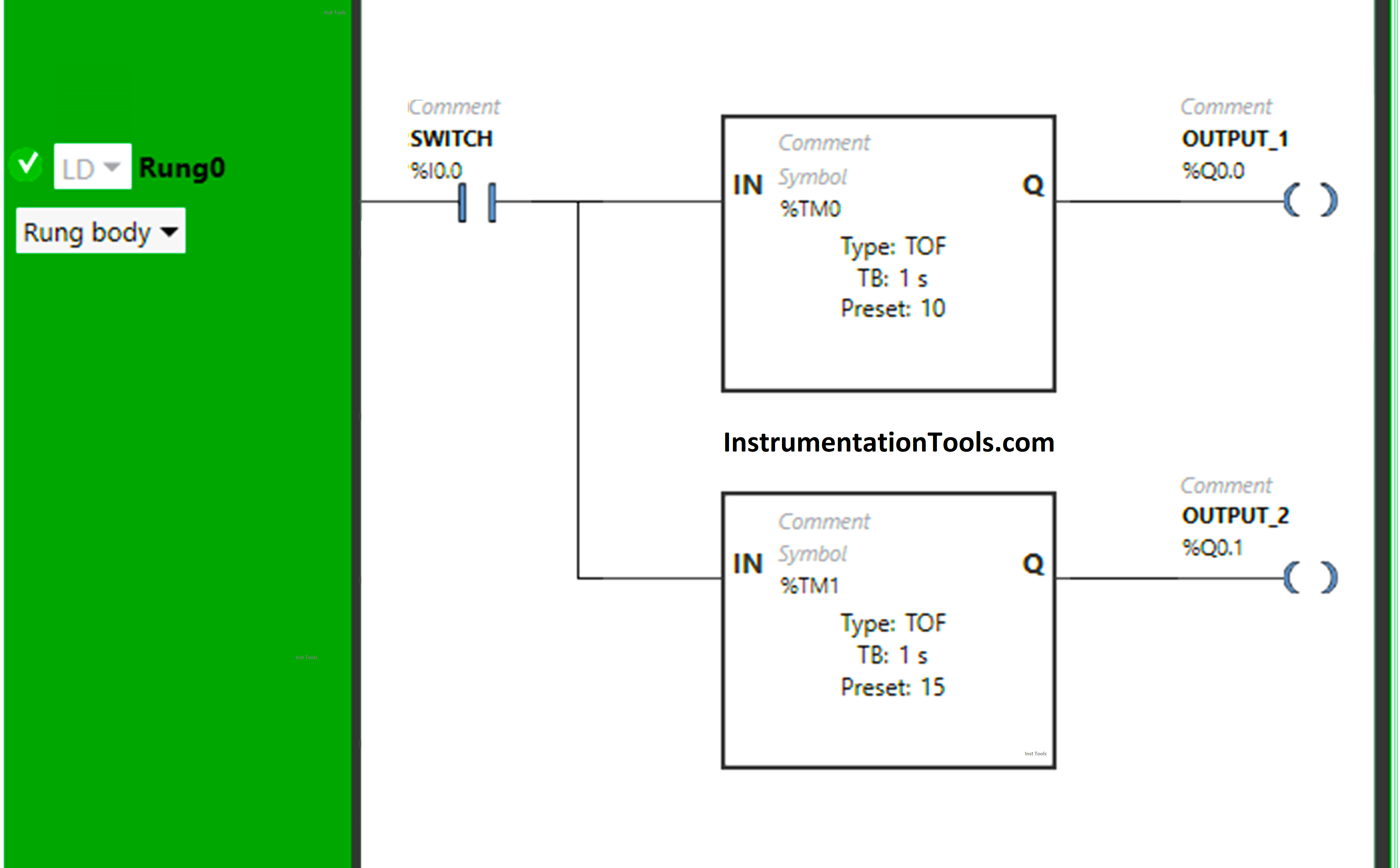
PLC Example on Switch Program with Timers

Program Description

We have used Normally Open Contact for Switch (I0.0).

In Rung 0:

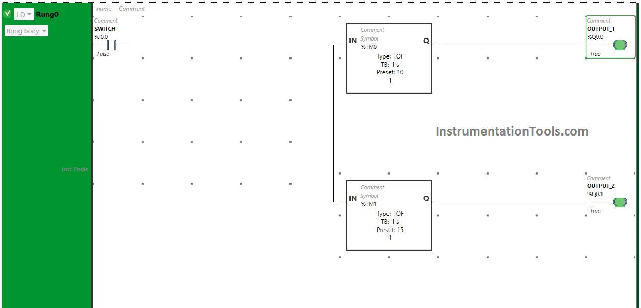
  1. Normally Open Contact is used for Switch (I0.0) to Turn ON Output 1 (Q0.0) and Output 2 (Q0.1).
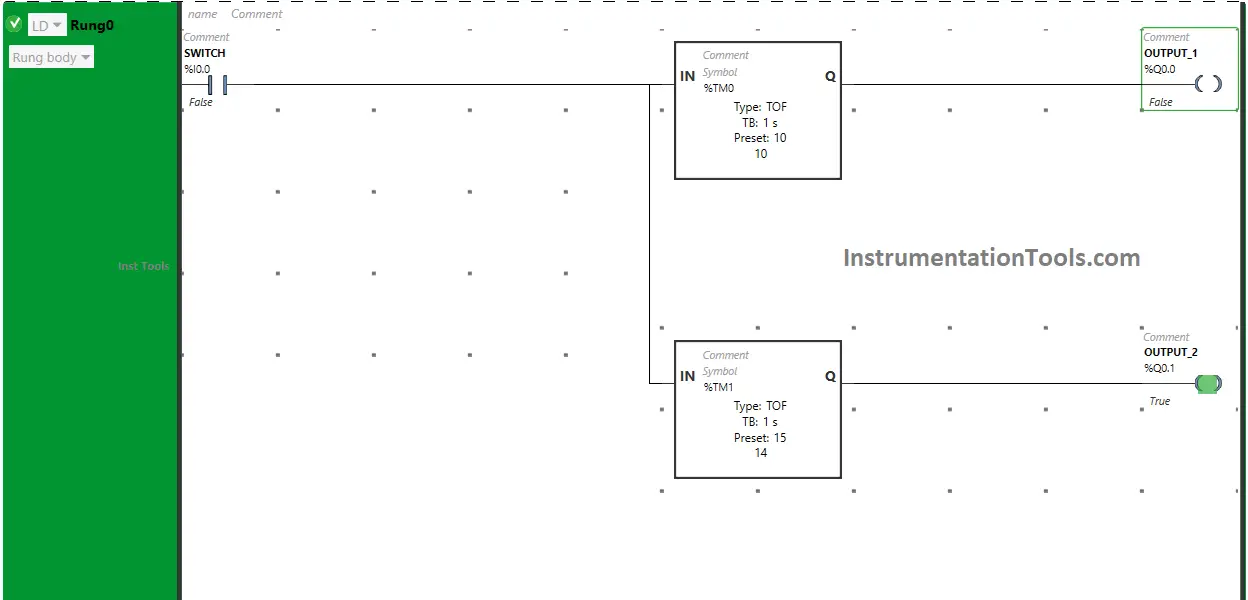
  2. Timer-type TOF is used to delay the turning OFF time of the Output 1 (Q0.0) for some time.
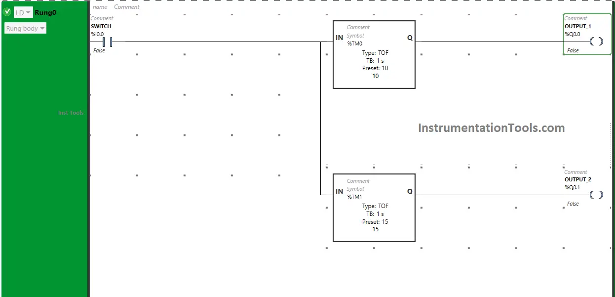
  3. Another Timer-type TOF is used to delay the turning OFF time of the Output 2 (Q0.0) for some time.

Simulation Result

Now we simulate the PLC program and check the results.

When Switch (I0.0) is turned ON
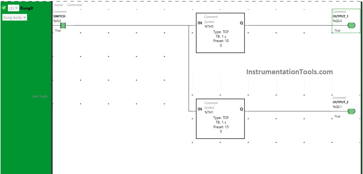
PLC programs that use timers and switches

When Switch (I0.0) is turned ON, the signal will flow through Switch (I0.0) as Normally Open Contact used for Switch (I0.0) will be in True State and Output 1 (Q0.0) & Output 2 (Q0.1) will turn ON.

When Switch (I0.0) is turned OFF
Switches and Timers in PLC

 When Switch (I0.0) is turned OFF, the output 1 (Q0.0) remains ON but for a limited time because Timer Function Block type TOF is used to delay the turning OFF time of the output 1 (Q0.0) and time is set to 10 seconds.
Timers in PLC and ladder logic program

After 10 seconds, the output 1 (Q0.0) will turn OFF.

Also, When Switch (I0.0) is turned OFF, the output 2 (Q0.0) remains ON but for limited time because another Timer Function Block type TOF is used to delay the turning OFF time of the output 2 (Q0.0) and time is set to 15 seconds.

After 15 seconds, the output 2 (Q0.0) will turn OFF.
Examples of Timers in PLC Logic

If you liked this article, please subscribe to our YouTube Channel for PLC and SCADA video tutorials.

You can also follow us on Facebook and Twitter to receive daily updates.

Read Next:

  • PLC Program for Two-Way Switch Logic
  • PLC Scaling Program for Control Valve
  • PLC Automatic Pedal Switch Program
  • PLC Programming using Limit Switch
  • Making Multi-Way Switches using PLC
Don't Miss Our Updates
Be the first to get exclusive content straight to your email.
We promise not to spam you. You can unsubscribe at any time.
Invalid email address
You've successfully subscribed !

Continue Reading

Siemens PLC programming: BCD, Integer, Double Integer, Real
How to use JUMP Instruction in PLC Ladder Logic?
PLC Program for Entry and Exit Control of Car Parking
How to Take Program Backup from Physical PLC? – Siemens PLC
Communicating Between Siemens PLC and Other PLC Brands
FIFO Instruction in Allen Bradley PLC Programming
Share This Article
Facebook Whatsapp Whatsapp LinkedIn Copy Link
Share
Leave a Comment

Leave a Reply Cancel reply

Your email address will not be published. Required fields are marked *

Stay Connected

128.3kFollowersLike
69.1kFollowersFollow
210kSubscribersSubscribe
38kFollowersFollow

Categories

Explore More

Examples of SCADA and PLC Configuration Systems
Basic Arithmetic Programming in Mitsubishi PLC
Product Painting PLC Program using Omron CX-Programmer
Laws of Boolean Algebra using Ladder Logic
Conveyor Speed Logic using Structured Text in PLC
PLC Programming Example on Bottle Line Control
Understanding Braking Theory in VFD
Examples of PLC Programming using Boolean Functions

Keep Learning

UDT in the PLC Programming

Implement UDT in PLC Programming: User-Defined Data Type

PLC Programming Example on Multi-Motor Control for Beginners

PLC Programming Example on Multi-Motor Control for Beginners

Programmable Logic Controller Quiz

Programmable Logic Controller Quiz

Sequential Timer Control of Lamps

Schneider PLC Example: Control Lamps Sequences

CRA Module in Schneider PLC

CRA Module in Schneider PLC – Remote IO Adapter Module

PLC Count values higher than 999

PLC Count values higher than 999

Learn PLC in Hindi

Learn PLC in Hindi

Automatic Box Filling System using PLC Programming

Automatic Box Filling System using PLC Programming

Learn More

UX Design

How to Achieve Sustainability in UX Design and Make a Difference?

Best Software to Use to Improve Your Business

Best Software to Use in 2023 to Help Improve the Effectiveness of Your Business

Speed Control of Pneumatic Cylinder (Explanation with PLC)

Speed Control of Pneumatic Cylinder (Explanation with PLC)

Electric Circuits Objective Questions

Electric Circuits Objective Questions – Set 12

HVAC Multiple Choice Questions

HVAC Multiple Choice Questions

Siemens PLC Math Instructions

Siemens PLC Mathematics Instructions

Control Systems Questions & Answers

Control Systems Objective Questions & Answers – Set 6

Level Gauge Theory

Types of Level Gauges

Menu

  • About
  • Privacy Policy
  • Copyright

Quick Links

  • Learn PLC
  • Helping Hand
  • Part Time Job

YouTube Subscribe

Follow US
All rights reserved. Reproduction in whole or in part without written permission is prohibited.
Welcome Back!

Sign in to your account

Username or Email Address
Password

Lost your password?