Inst ToolsInst ToolsInst Tools
  • Courses
  • Automation
    • PLC
    • Control System
    • Safety System
    • Communication
    • Fire & Gas System
  • Instrumentation
    • Design
    • Pressure
    • Temperature
    • Flow
    • Level
    • Vibration
    • Analyzer
    • Control Valve
    • Switch
    • Calibration
    • Erection & Commissioning
  • Interview
    • Instrumentation
    • Electrical
    • Electronics
    • Practical
  • Q&A
    • Instrumentation
    • Control System
    • Electrical
    • Electronics
    • Analog Electronics
    • Digital Electronics
    • Power Electronics
    • Microprocessor
  • Request
Search
  • Books
  • Software
  • Projects
  • Process
  • Tools
  • Basics
  • Formula
  • Power Plant
  • Root Cause Analysis
  • Electrical Basics
  • Animation
  • Standards
  • 4-20 mA Course
  • Siemens PLC Course
Reading: Water Fountain Control Logic – PLC Exercises and Solutions
Share
Font ResizerAa
Inst ToolsInst Tools
Font ResizerAa
  • Courses
  • Design
  • PLC
  • Interview
  • Control System
Search
  • Courses
  • Automation
    • PLC
    • Control System
    • Safety System
    • Communication
    • Fire & Gas System
  • Instrumentation
    • Design
    • Pressure
    • Temperature
    • Flow
    • Level
    • Vibration
    • Analyzer
    • Control Valve
    • Switch
    • Calibration
    • Erection & Commissioning
  • Interview
    • Instrumentation
    • Electrical
    • Electronics
    • Practical
  • Q&A
    • Instrumentation
    • Control System
    • Electrical
    • Electronics
    • Analog Electronics
    • Digital Electronics
    • Power Electronics
    • Microprocessor
  • Request
Follow US
All rights reserved. Reproduction in whole or in part without written permission is prohibited.
Inst Tools > Blog > PLC Tutorials > Water Fountain Control Logic – PLC Exercises and Solutions

Water Fountain Control Logic – PLC Exercises and Solutions

Learn the water fountain control logic using the PLC timers programming to control the high and low spray modes.

Last updated: April 17, 2024 7:06 pm
Editorial Staff
PLC Tutorials
No Comments
Share
6 Min Read
SHARE

Learn the water fountain control logic using the PLC timers programming to control the high and low spray modes.

Contents
Water Fountain Control LogicPLC Exercises and SolutionsInputs and OutputsLadder DiagramProgram DescriptionPLC Result

Please note that this PLC programming example is provided for educational purposes and allows learners to go through the practical usage of ladder logics.

Water Fountain Control Logic

Problem Statement:

Design a PLC ladder logic for the following application.

We are using one toggle switch to control High-Spray and Low-Spray.

The water fountain should operate in three stages or modes, as mentioned below.

  • High Spray for 15 seconds.
  • Low Spray for 10 seconds.
  • OFF for 5 seconds.

PLC Exercises and Solutions

These PLC exercises and solutions offer you the opportunity to learn the programming with in-depth concepts.

This PLC video helps you to understand the water fountain program.

PLC Exercises and Solutions - Water Fountain Example

Inputs and Outputs

Digital Inputs:

Start Button: I0.0

Digital Outputs:

High Spray: Q0.0

Low Spray: Q0.1

Ladder Diagram
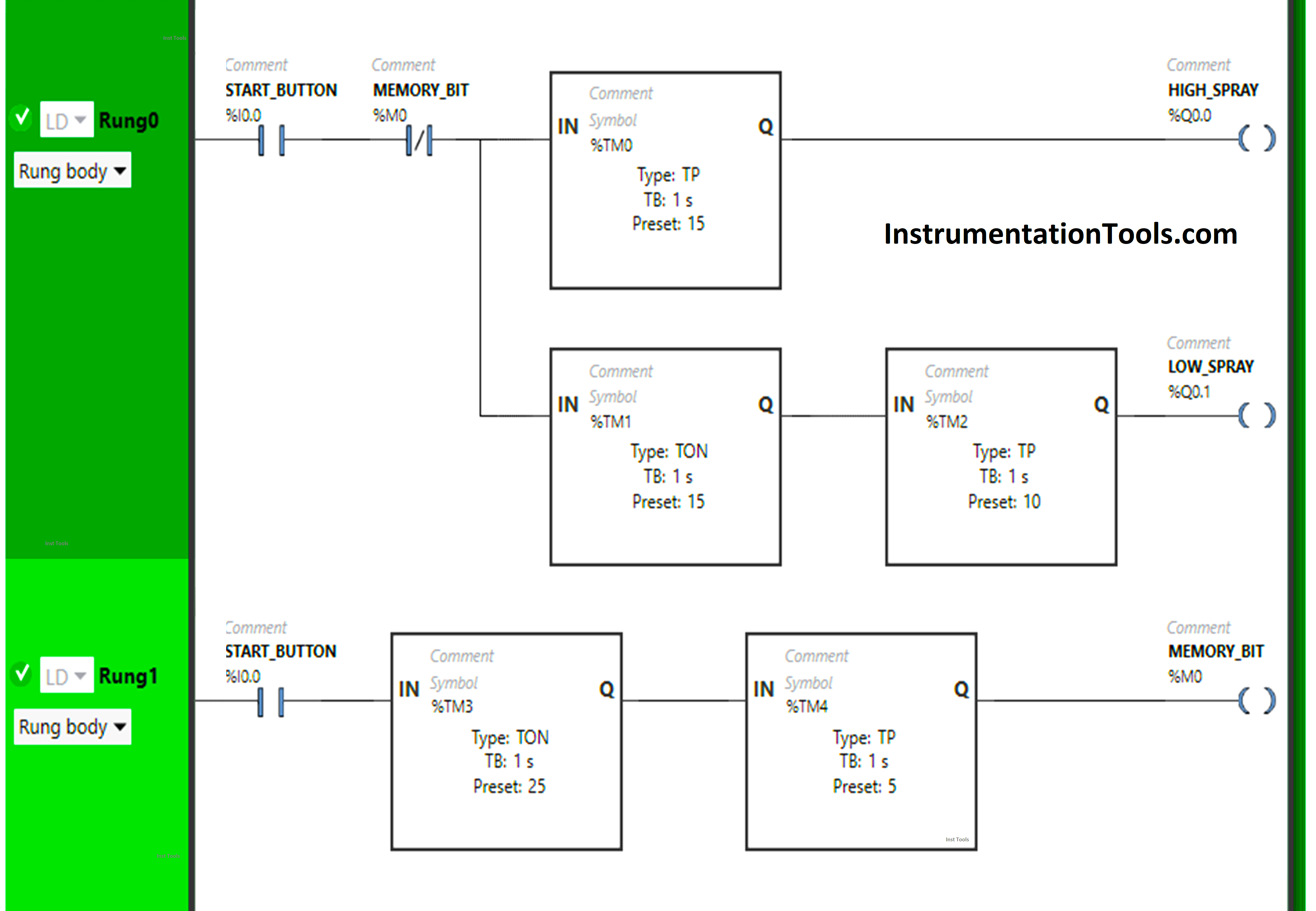
Water Fountain Control Logic

Program Description

We have used Normally Open Contact for the Start Button (I0.0).

We have used Normally Closed Contact for Memory Bit (M0).

In Rung 0:

  1. Normally Open Contact is used for the Start Button (I0.0) to Turn ON the outputs High Spray (Q0.0) and Low Spray (Q0.1).
  2. Normally Closed Contact is used for Memory Bit (M0) to Turn OFF the outputs High Spray  (Q0.0) and Low Spray (Q0.1).
  3. Timer-type TP is used to Turn ON the output High Spray (Q0.0) for a limited time.
  4. Timer-type TON is used to delay the turning ON time of the output Low Spray (Q0.1) for some time.
  5. Timer-type TP is used to Turn ON the output Low Spray (Q0.1) for a limited time.

In Rung 1:

  1. Normally Open Contact is used for the Start Button (I0.0) to Turn ON Memory Bit (M0). 
  2. Timer-type TON is used to delay the turning ON time of Memory Bit (M0) for some time.
  3. Timer-type TP is used to Turn ON the Memory Bit (M0) for a limited time.

PLC Result

Now we will simulate the PLC logic and discuss the results.

Rung 0:
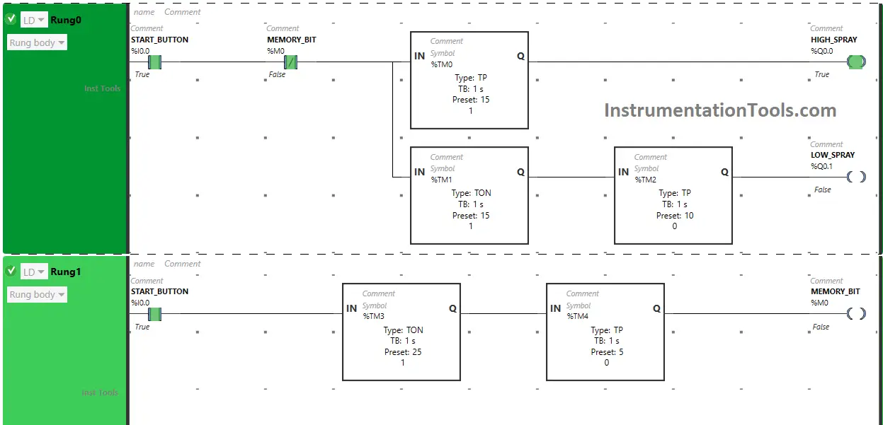
PLC used for water fountain pump control

When the Start Button (I0.0) is turned ON, the output High Spray (Q0.0) will turn ON for 15 seconds as Timer Function Block type TP is used to Turn ON the output High Spray (Q0.0) for a limited time. The time is set to 15 seconds.
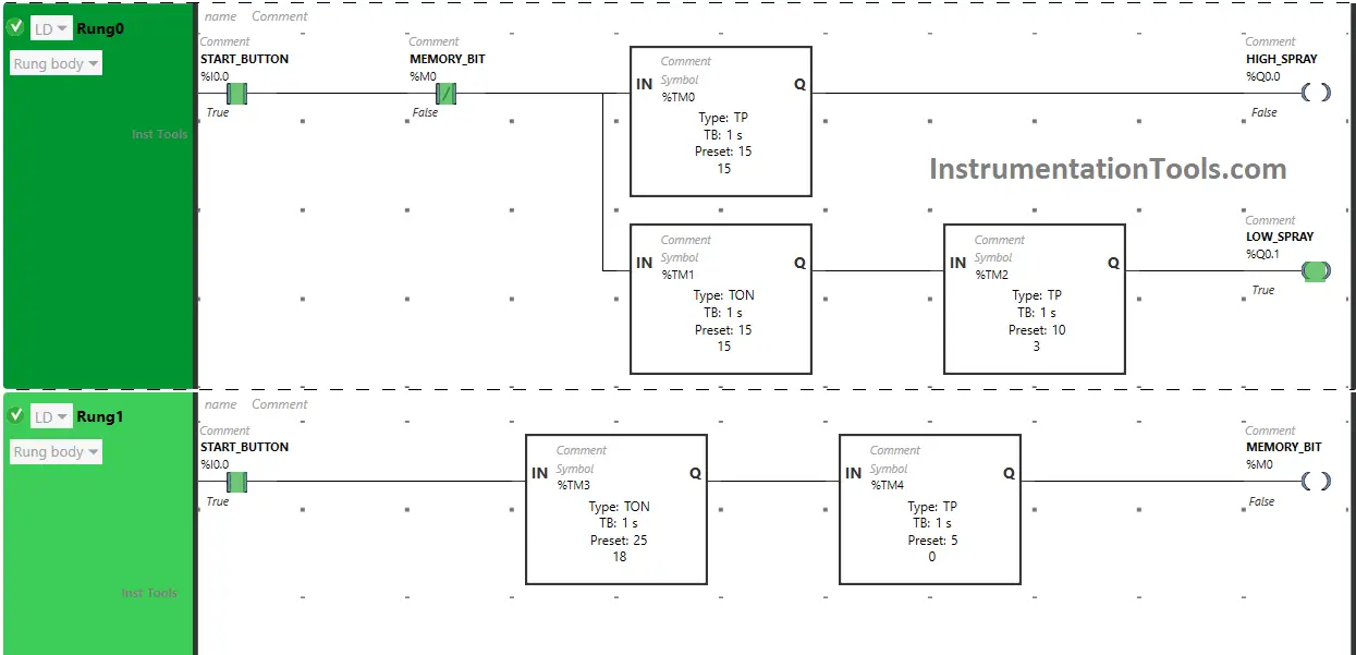
water fountain example ladder logic

After 15 seconds, the output High Spray (Q0.0) will turn OFF. Also, when the Start Button (I0.0) is turned ON, the output Low Spray (Q0.1) will turn ON after 15 seconds, (i.e immediately when the output High Spray (Q0.0) turns OFF) as Timer Function Block TON is used to delay the turning ON time of the output Low Spray (Q0.1). The time is set to 15 seconds.
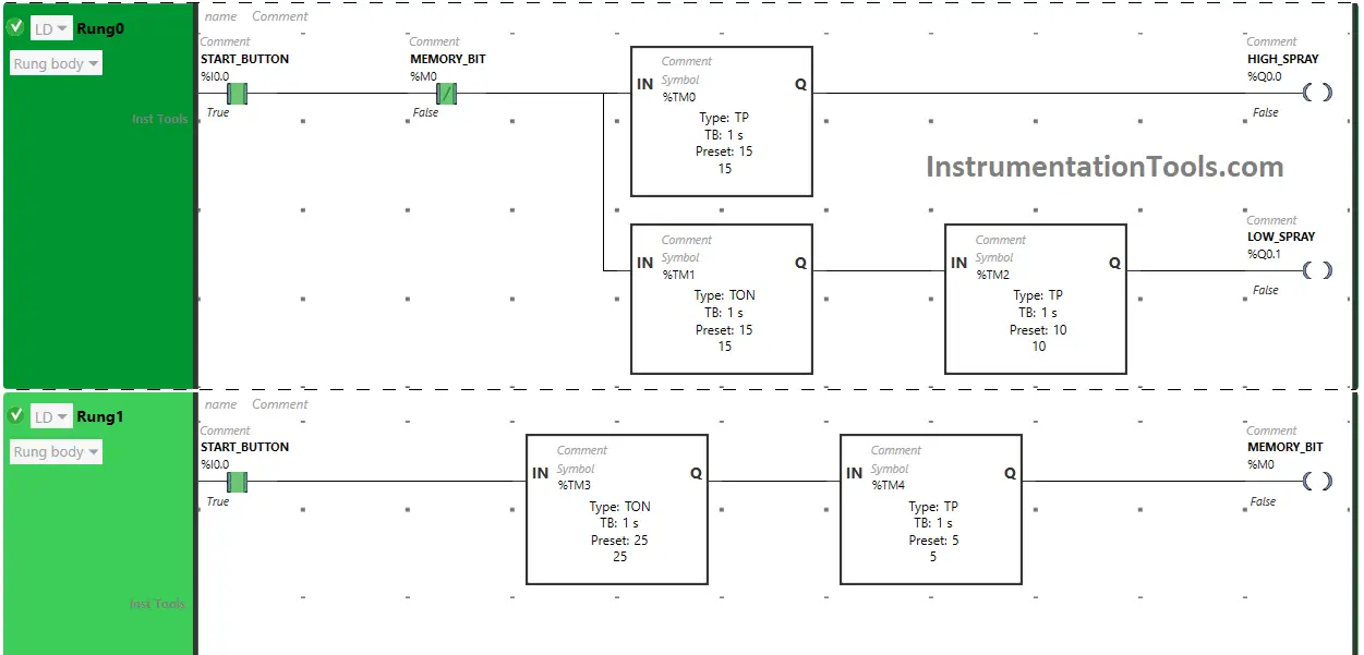
PLC Programming for Fountain

After 15 seconds, the Low Spray  (Q0.1) will turn ON but only for 10 seconds as Timer Function Block type TP is used to Turn ON the output Low Spray (Q0.1) for limited time. The time is set to 10 seconds. After 10 seconds, the output Low Spray (Q0.1) will turn OFF.

Rung 1:

When the Start Button (I0.0) is turned ON, the Memory Bit (M0) will turn ON after 25 seconds  (i.e immediately when the output Low Spray (Q0.1) turns OFF) as Timer Function Block TON is used to delay the turning ON time of Memory Bit (M0). The time is set to 25 seconds.
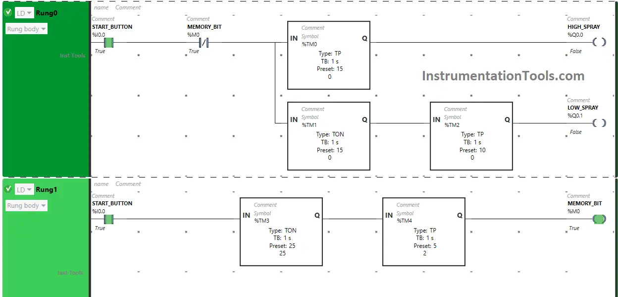
PLC Exercises and Solutions with Example

After 25 seconds, Memory Bit (M0) will turn ON but only for 5 seconds as Timer Function Block type TP is used to Turn ON Memory Bit (M0) for a limited time. The time is set to 5 seconds. After 5 seconds,  Memory Bit (M0) will turn OFF.

When Memory Bit (M0) turns ON in Rung1, Normally Closed Contact used for Memory Bit (M0) in Rung0 i.e used to turn OFF both outputs High Spray (Q0.0) and Low Spray (Q0.1) will be in True state and does not allow signal to pass to the outputs High Spray (Q0.0) and Low Spray (Q0.1) and the outputs High Spray (Q0.0) and Low Spray (Q0.1) will turn OFF.
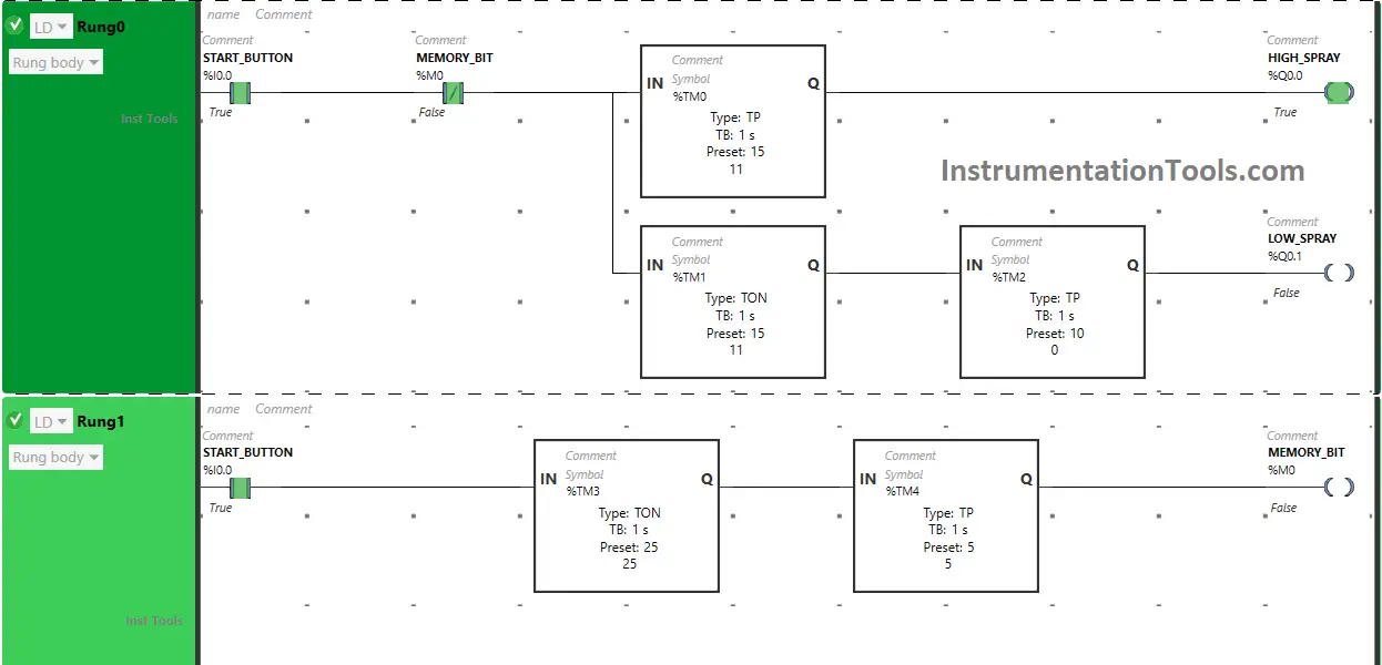
Programmable Logic Controller Water Fountain

When the timer reaches its set time in Timer Function Block type TP in Rung1, Memory Bit (M0) turns OFF. When Memory Bit (M0) turns OFF in Rung1, Normally Closed Contact used for Memory Bit (M0) in Rung0  will be in a false state and will allow the signal to pass to the outputs  High Spray (Q0.0) and Low Spray (Q0.1) and the outputs High Spray (Q0.0) and Low Spray (Q0.1) will turn ON again.

If you liked this article, please subscribe to our YouTube Channel for PLC and SCADA video tutorials.

You can also follow us on Facebook and Twitter to receive daily updates.

Read Next:

  • PLC Logic for Stairway Lighting
  • Data Sharing Between PLC Systems
  • PLC Programming for Barrier Control
  • Traffic Lights PLC Logic using Timers
  • Control Spray Nozzle, Fans, Puncher
Don't Miss Our Updates
Be the first to get exclusive content straight to your email.
We promise not to spam you. You can unsubscribe at any time.
Invalid email address
You've successfully subscribed !

Continue Reading

Automatic Packing of Bottles Programming
VFD Commissioning and Testing Procedure (Variable Frequency Drive)
Example PLC Program
How to Use Encode and Decode Instructions in PLC ?
Interconnection between PLC, MCC, LCP & Pumps – Video
S7-1200 Hardware Configuration – Siemens PLC Tutorials
Share This Article
Facebook Whatsapp Whatsapp LinkedIn Copy Link
Share
Leave a Comment

Leave a Reply Cancel reply

Your email address will not be published. Required fields are marked *

Stay Connected

128.3kFollowersLike
69.1kFollowersFollow
210kSubscribersSubscribe
38kFollowersFollow

Categories

Explore More

HMI Handbook
Automatic Coffee Vending Machine – PLC Logic Programming
PLC Functional Block Diagram for Logic Gates
Alarm Acknowledge using PLC
Difference Between PLCSIM and PLCSIM Advanced? – Siemens PLC
Explaining Various Types of Analog Instruments
Troubleshoot the Status of a PLC Via CPU Indicators
SCADA System Vulnerabilities

Keep Learning

Configure Analog Inputs and Outputs in Delta PLC

How to Configure Analog Inputs and Outputs in Delta PLC?

PLC Digital Inputs

PLC Digital Input and Digital Output Modules

PLC program for bread oven

Bread Oven Control in Auto and Manual Modes PLC Program

PLC Program for Blinking Lamp on 5 Seconds Interval

PLC Program for Blinking Lamp on 5 Seconds Interval

Fixed PLC

#19 PLC Best Practices – Monitor PLC Memory Usage

Components of SCADA

Components of SCADA

Free Allen Bradley PLC Training Course

Free Allen Bradley PLC Ladder Logic Training Course

Siemens PLC Programming OBs in Siemens TIA Portal

FC Function in Siemens PLC

Learn More

Power Electronics Objective Questions

Voltage Control in Inverters Objective Questions

TIA Portal MOVE Instruction

MOVE Instruction in PLC – What You Need to Know?

Hydraulic Systems Objective Questions

Hydraulic Systems Objective Questions

Pressure and Temperature Gauges

Pressure and Temperature Gauges

Flow Transmitter Output Current Calculation

Calculate Flow Transmitter Output Current

CAN Protocol with the OSI Model

Basics for CAN Bus Protocol – Controller Area Network

Differential Pressure Switch Principle

Differential Pressure Switch Principle

Switches, Repeaters, Bridges, Routers, Firewalls

Purpose of Gateways, Bridges & Routers in Networking

Menu

  • About
  • Privacy Policy
  • Copyright

Quick Links

  • Learn PLC
  • Helping Hand
  • Part Time Job

YouTube Subscribe

Follow US
All rights reserved. Reproduction in whole or in part without written permission is prohibited.
Welcome Back!

Sign in to your account

Username or Email Address
Password

Lost your password?