PLC programming for traffic barrier control to raise or lower the barrier whenever the vehicle arrives or departures.
Disclaimer: We advise individuals to approach this PLC programming example with the understanding that it is designed for educational purposes and for learning the ladder logic principles through practical exercises.
Traffic Barrier Control
Problem Statement:
Design a PLC ladder logic for the following application.
We are using one toggle switch to control the Barrier.
When a vehicle arrives, raise the barrier for 20 seconds, and after that lower the barrier.
If the barrier hits during lowering, immediately raise the barrier for 5 seconds again.
Industrial PLC Training Video
Industrial PLC training videos help beginners learn different manufacturers’ PLC programming.
Inputs and Outputs
Digital Inputs:
P-Sensor: I0.0
Digital Outputs:
Barrier: Q0.0
PLC Programming
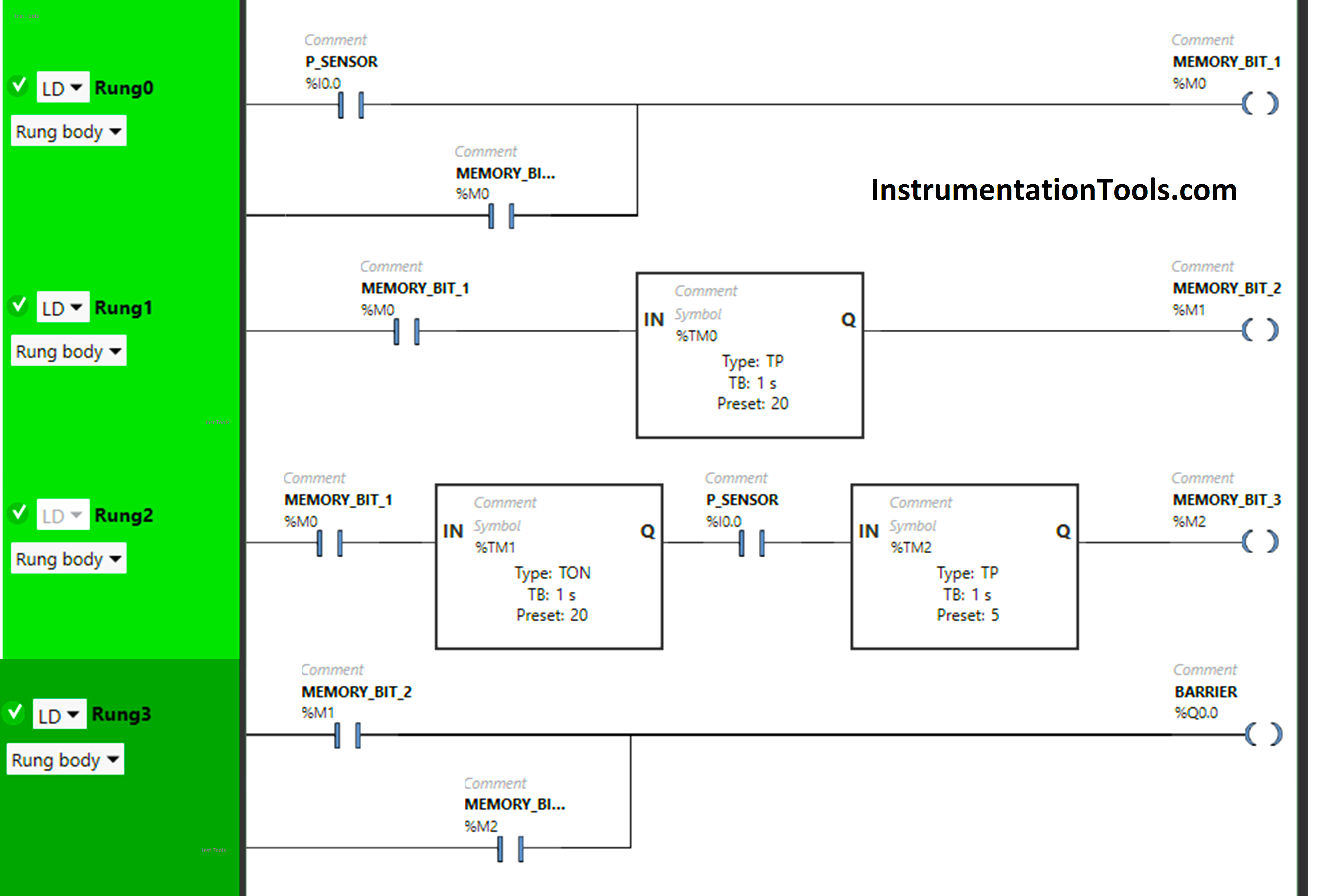
Program Description
We have used Normally Open Contacts for P-Sensor(I0.0) and Memory Bits.
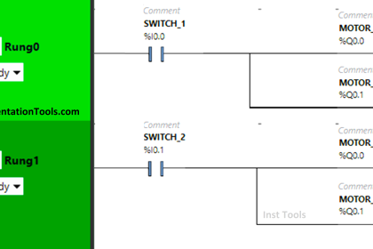
In Rung 0:
- Normally Open Contact is used for P-Sensor (I0.0) to Turn ON Memory Bit 1 (M0).
- Memory Bit 1 (M0) is latched so that when the P-sensor (I0.0) turns OFF, Memory Bit 1 (M0) still remains ON.
In Rung 1:
- Normally Open Contact is used for Memory Bit 1 (M0) to Turn ON Memory Bit 2 (M1).
- Timer TP is used to Turn ON Memory Bit 2 (M1) for a limited time.
In Rung 2:
- Normally Open Contact is used for Memory Bit 1 (M0) and P-Sensor(I0.0) to Turn ON Memory Bit 3(M2).
- Timer TON is used to delay the turning ON time of Memory Bit 3(M2) for some time.
- Timer TP is used to Turn ON Memory Bit 3(M2) for a limited time.
In Rung 3:
- Normally Open Contact is used for Memory Bit 2 (M1) and Memory Bit 3 (M2) to Turn ON the output Barrier (Q0.0).
- Memory Bit 2 (M1) and Memory Bit 3 (M2) are connected in parallel, thus implementing OR Logic Gate.
Simulation
Now we simulate the above PLC program and see its result with different input statuses.
When P-Sensor detects a car or When a car arrives:
When P-Sensor (I0.0) detects a car ( when a car arrives), Memory Bit 1 (M0) turns ON and stores the data that the car has arrived as Memory bits store the data. Memory Bit 1 (M0) is latched so that when the P-sensor (I0.0) turns OFF, Memory Bit 1 (M0) still remains ON.
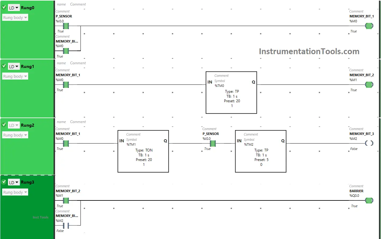
When Memory Bit 1 (M0) turns ON in Rung0, Normally Open Contact used for Memory Bit 1 (M0) in Rung1 will be in True State and will pass the signal to turn ON Memory Bit 2 (M1) but only for 20 seconds as Timer Function Block type TP is used to turn ON the Memory Bit 2 (M1) for Limited time. The time is set to 20 seconds. After 20 seconds, Memory Bit 2 (M1) will turn OFF.
When Memory Bit 2 ( M1) turns ON in Rung1, Normally Open Contact used for Memory Bit 2 (M1) in Rung3 used to turn ON the output Barrier (Q0.0) will be in True State and will pass the signal to turn ON the output Barrier (Q0.0) (Barrier Raised).
In Rung1, when Timer Function Block type TP reaches its set time i.e 20 seconds, Memory Bit 2 (M1) will turn OFF in both Rung1 & Rung3, and when Memory Bit 2 (M1) turns OFF in Rung3, the output Barrier (Q0.0) turns OFF ( Barrier starts lowering).
If the P-Sensor detects a car again or If the barrier hits during lowering:
When Memory Bit 1 (M0) turns ON in Rung0, Normally Open Contact used for Memory Bit 1 (M0) in Rung2 will be in True State and will pass the signal to turn ON Memory Bit 3 (M2) after 20 seconds ( i.e immediately when Memory Bit 2 (M1) turns OFF in Rung1 as Timer Function Block type TON is used to delay the turning ON time of the Memory Bit 3 (M2) and when P-Sensor detects a car again or ( when barrier hits during lowering).
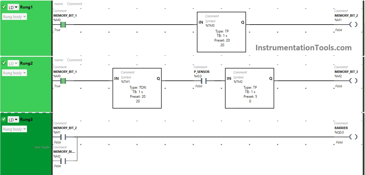
So after 20 seconds when the P-sensor detects a car again or ( barrier hits during lowering), Memory Bit 3 (M2) turns ON for 5 seconds because Timer Function Block type TP is used to turn ON the Memory Bit 3 (M2) for a Limited time. The time is set to 5 seconds. After 5 seconds, Memory Bit 3 (M2) will turn OFF.
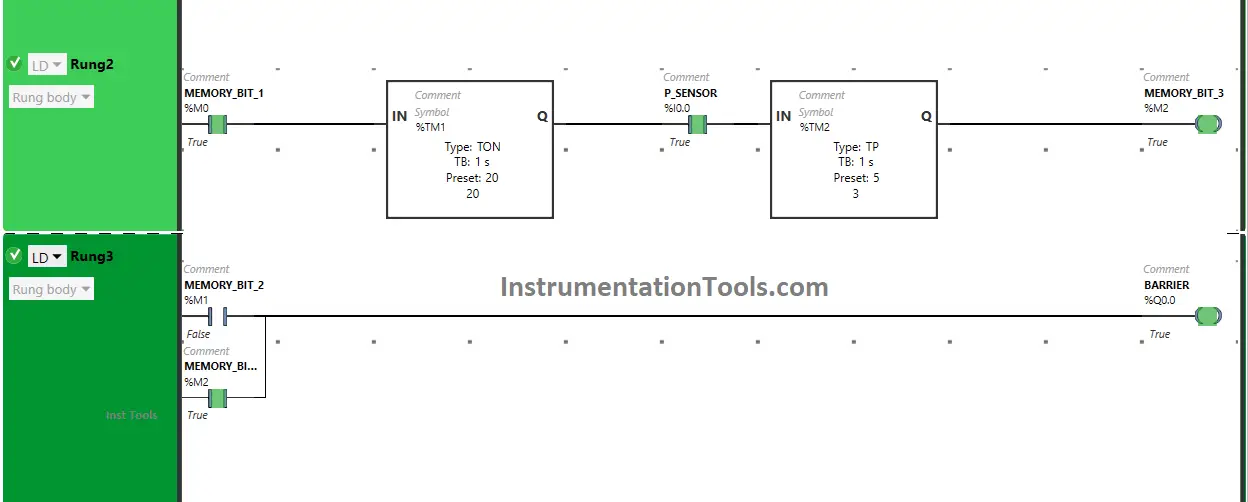
When Memory Bit 3 ( M2) turns ON in Rung2, Normally Open Contact used for Memory Bit 3 (M2) in Rung3 used to turn ON the output Barrier (Q0.0) will be in True State and will pass the signal to turn ON the output Barrier (Q0.0) (Barrier Raised).
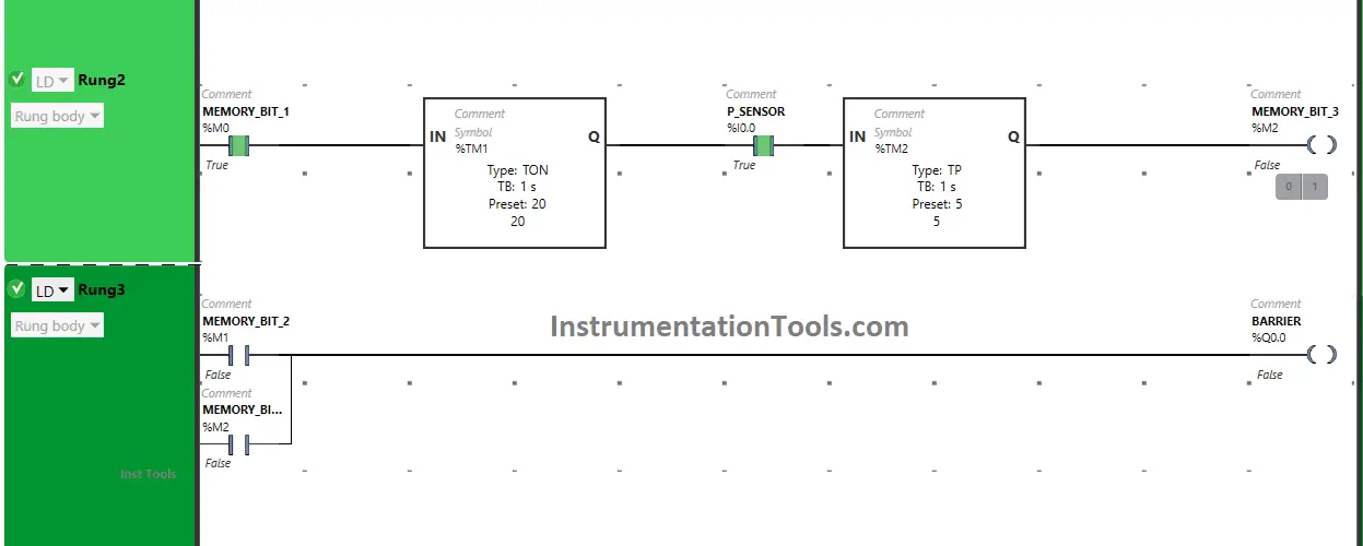
In Rung2, when Timer Function Block type TP reaches its set time i.e 5 seconds, Memory Bit 3 (M2) will turn OFF in both Rung2 & Rung3 and when Memory Bit 3 (M2) turns OFF in Rung3, the output Barrier (Q0.0) turns OFF ( Barrier starts lowering).
If you liked this article, please subscribe to our YouTube Channel for PLC and SCADA video tutorials.
You can also follow us on Facebook and Twitter to receive daily updates.
Read Next:
- What is a Retro-Reflective Sensor?
- PLC Examples Industrial Automation
- PLC Retrofitting Project Importance
- VFD Interview Questions and Answers
- Multi-touch Technology Automation