Inst ToolsInst ToolsInst Tools
  • Ask
  • Courses
  • Videos
  • Q & A
    • Interview
      • Instrumentation
      • Electronics
      • Electrical
      • Practical Questions
    • MCQ
      • Instrumentation MCQ
      • Electrical MCQ
      • Electronics MCQ
      • Control Systems MCQ
      • Analog Electronics MCQ
      • Digital Electronics MCQ
      • Power Electronics MCQ
      • Microprocessor MCQ
      • Multiple Choice Questions
  • EE
    • Electronics
      • Electronics Q & A
      • Electronic Basics
      • Electronic Devices & Circuits
      • Electronics Animation
      • Digital Electronics
    • Electrical
      • Electrical Basics
      • Electrical Q & A
      • Power Electronics
      • Electrical Machines
      • Electrical Animation
      • Power Systems
      • Switchgear & Protection
      • Transmission & Distribution
  • Measure
    • Control Valves
    • Calibration
    • Temperature
    • Pressure
    • Flow
    • Level
    • Analyzers
    • Switches
    • Vibration
    • Solenoid Valve
  • Control
    • PLC Tutorials
    • Control Systems
    • Safety Instrumented System (SIS)
    • Communication
    • Fire & Gas System
  • More
    • Design
    • Tools
    • Animation
    • Basics
    • Formulas
    • Standards
    • TextBooks
    • Common
    • Software
    • Excel Tools
    • Erection & Commissioning
    • Process Fundamentals
    • Videos
    • Books
Search
All rights reserved. Reproduction in whole or in part without written permission is prohibited.
Reading: PLC Example on Manufacturing Line Assembly
Share
Notification Show More
Font ResizerAa
Inst ToolsInst Tools
Font ResizerAa
  • Courses
  • PLC Tutorials
  • Control Systems
Search
  • Ask
  • Courses
  • Videos
  • Q & A
    • Interview
    • MCQ
  • EE
    • Electronics
    • Electrical
  • Measure
    • Control Valves
    • Calibration
    • Temperature
    • Pressure
    • Flow
    • Level
    • Analyzers
    • Switches
    • Vibration
    • Solenoid Valve
  • Control
    • PLC Tutorials
    • Control Systems
    • Safety Instrumented System (SIS)
    • Communication
    • Fire & Gas System
  • More
    • Design
    • Tools
    • Animation
    • Basics
    • Formulas
    • Standards
    • TextBooks
    • Common
    • Software
    • Excel Tools
    • Erection & Commissioning
    • Process Fundamentals
    • Videos
    • Books
Follow US
All rights reserved. Reproduction in whole or in part without written permission is prohibited.
Inst Tools > Blog > PLC Tutorials > PLC Example on Manufacturing Line Assembly

PLC Example on Manufacturing Line Assembly

This PLC example on manufacturing line assembly is an intermediate-level PLC program prepared for the students to learn the programming.

Last updated: April 10, 2024 3:23 pm
Editorial Staff
PLC Tutorials
No Comments
Share
9 Min Read
SHARE

This PLC example on manufacturing line assembly is an intermediate-level PLC program prepared for the students to learn the programming.

Contents
Manufacturing Line AssemblyPLC Programming TrainingPLC Program InputsPLC Program OutputsLadder LogicLogic ExplanationTest ResultsWhen the Product reaches station 1When the Product reaches station 2When the Product reaches station 3

Note: The PLC programming example is specifically prepared for the students to learn the PLC programs.

Manufacturing Line Assembly

Problem Statement

Design a PLC ladder logic for the following application.

We are using one toggle switch and three sensors to control 3 stations.

The product should move through 3 assembly stations, with each station operating for 15 seconds.

PLC Programming Training

Watch the video below to understand the PLC program objective in detail and its solution.

PLC Program Inputs

The PLC program inputs are shown below.

Start Button: I0.0

Sensor 1: I0.1

Sensor 2: I0.2

Sensor 3: I0.3

PLC Program Outputs

The PLC program outputs are shown below.

Station  1: Q0.0

Station 2: Q0.1

Station 3: Q0.2

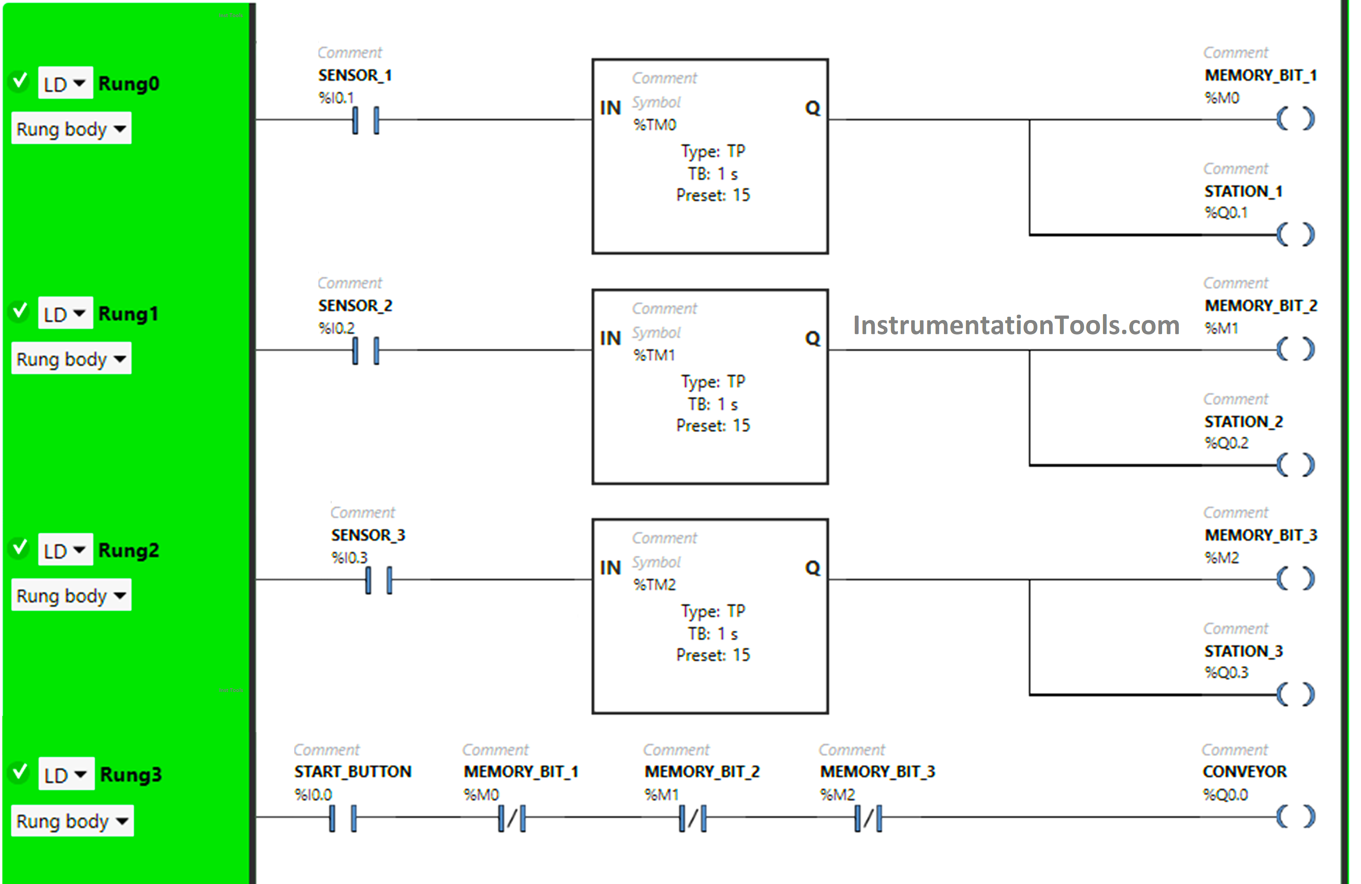
Ladder Logic
PLC Example on Manufacturing Line Assembly
Fig: 1

Logic Explanation

We have used Normally Open Contacts for Start Button(I0.0), Sensor 1 (I0.1), Sensor 2 (I0.2), and Sensor 3 (Q0.3).

In Rung0:

1) Normally Open Contact is used for Sensor 1 (I0.1) to Turn ON  Memory Bit 1 (M0) and the output station 1 (Q0.1).

2) Timer Function Block type TP is used to Turn ON Memory Bit 1 (M0) and the output station 1 (Q0.1) for a limited time.

In Rung1:

1) Normally Open Contact is used for Sensor 2 (I0.2) to Turn ON  Memory Bit 2 (M1) and the output station 2 (Q0.2).

2) Timer Function Block type TP is used to Turn ON Memory Bit 2 (M1) and the output station 2 (Q0.2) for a limited time.

In Rung2:

1) Normally Open Contact is used for Sensor 3 (I0.3) to Turn ON  Memory Bit 3 (M2) and the output station 3 (Q0.3).

2) Timer Function Block type TP is used to Turn ON Memory Bit 3 (M2) and the output station 3 (Q0.3) for a limited time.

In Rung3:

1) Normally Open Contact is used for the Start Button (I0.0) to Turn ON  the output Conveyor (Q0.0).

2) Normally Closed Contacts are used for Memory Bit 1 (M0), Memory Bit 2 (M1), and Memory Bit 3 (M2) to Turn ON  the output Conveyor (Q0.0).

Test Results

Let’s simulate our PLC logic and show the results below. Note: we showed the part of the simulation logic instead of the complete program.

When the Product reaches station 1

PLC in Automotive Manufacturing
Fig: 2
PLC Integration in Manufacturing Assembly
Fig: 3
Programming a Production & Assembly Line Ladder Logic
Fig: 4
Automatic Production Line Training
Fig: 5
program for Manufacturing Assembly
Fig: 6

When the Start Button (I0.0) is turned ON in Rung3, the output Conveyor (Q0.0) turns ON ( Conveyor starts moving) as Normally Open Contact used for start Button (I0.0) will be in True state and passes the signal to turn ON the output Conveyor (Q0.0).

In the False state, Normally Closed Contacts used Memory Bit 1 (M0), Memory Bit 2 (M1), and Memory Bit 3 (M2) in Rung3 will also pass the signal to turn ON the output Conveyor (Q0.0) and the output Conveyor (Q0.0) turns ON (Conveyor starts moving).

When Sensor 1 (I0.1) gets activated in Rung0 ( Product reaches Station 1), Memory Bit 1 (M0) turns ON, and also, the output Station 1 (Q0.1) turns ON (Machines at Station 1 starts working).

When Memory Bit 1 (M0) turns ON in Rung0, Normally Closed Contact used for Memory Bit 1 (M0) in Rung3 will be in a True state and does not allow the signal to pass through it and the Conveyor (Q0.0) turns OFF ( Conveyor stops at Station 1 ).

In Rung0, Memory Bit 1 (M0) and the output Station 1 (Q0.1) turn off after some time as  Timer Function Block type TP is used to Turn ON the output Station 1 (Q0.1) and Memory Bit 1 (M0) for a limited time. The time is set to 15 seconds.

After 15 s, the output Station 1 (Q0.1) and Memory Bit 1 (M0) will turn OFF (Machines at Station 1 finished their work).

When Memory Bit 1 (M0) turns OFF in Rung0, Normally Closed Contact used for Memory Bit 1 (M0) will be in a False state and allow the signal to pass through it and the output Conveyor (Q0.0) turns ON (Conveyor starts moving).

When the Product reaches station 2

Line Assembly using PLC Ladder Logic Programming
Fig: 7
Logic of PLCs in Manufacturing
Fig: 8
Assembly Line Using PLC Simulation
Fig: 9
PLC Programming for Automotive Industry
Fig: 10

After leaving Station 1, When Sensor 2 (I0.2) gets activated in Rung1 ( Product reaches Station 2), Memory Bit 2 (M1) turns ON, and also, the output Station 2 (Q0.2) turns ON (Machines at Station 2 starts working).

When Memory Bit 2 (M1) turns ON in Rung1, Normally Closed Contact used for Memory Bit 2 (M1) in Rung3 will be in a True state and does not allow the signal to pass through it and the Conveyor (Q0.0) turns OFF ( Conveyor stops at Station 2 ).

In Rung1, Memory Bit 2 (M1) and the output Station 2 (Q0.2) turn off after some time as  Timer Function Block type TP is used to Turn ON the output Station 2 (Q0.2) and Memory Bit 2 (M1) for a limited time.

The time is set to 15 seconds. After 15 s, the output Station 2 (Q0.2) and Memory Bit 2 (M1) will turn OFF (Machines at Station 2 finished their work).

When Memory Bit 2 (M1) turns OFF in Rung1, Normally Closed Contact used for Memory Bit 2 (M1) will be in a False state and allow the signal to pass through it and the output Conveyor (Q0.0) turns ON (Conveyor starts moving).

When the Product reaches station 3

PLC Production Line Example
Fig: 11
PLC Automation of assembly lines
Fig: 12
PLC Programming Industrial Automation Assembly Line
Fig: 13
Industrial Automation for Assembly Line with PLC
Fig: 14

After leaving Station 2, When Sensor 3 (I0.3) gets activated in Rung2 (Product reaches Station 3), Memory Bit 3 (M2) turns ON, and also, the output Station 3 (Q0.3) turns ON (Machines at Station 3 starts working).

When Memory Bit 3 (M2) turns ON in Rung2, Normally Closed Contact used for Memory Bit 3 (M2) in Rung3 will be in a True state and does not allow the signal to pass through it and the Conveyor (Q0.0) turns OFF ( Conveyor stops at Station 3 ).

In Rung2, Memory Bit 3 (M2) and the output Station 3 (Q0.3) turn OFF after some time as  Timer Function Block type TP is used to Turn ON the output Station 3 (Q0.3) and Memory Bit 3 (M2) for a limited time. The time is set to 15 seconds. After 15 s, the output Station 3 (Q0.3) and Memory Bit 3 (M2) will turn OFF (Machines at Station 3 finished their work).

When Memory Bit 3 (M2) turns OFF in Rung2, Normally Closed Contact used for Memory Bit 3 (M2) will be in a False state and allow the signal to pass through it and the output Conveyor (Q0.0) turns ON (Conveyor starts moving).

If you liked this article, please subscribe to our YouTube Channel for PLC and SCADA video tutorials.

You can also follow us on Facebook and Twitter to receive daily updates.

Read Next:

  • Timers in PLC Programming Tutorials
  • Latching and Unlatching in PLC Programming
  • Electrical Cabinet Air Conditioner Maintenance
  • Motor control using PLC Ladder Programming
  • User-Defined Data Types and Function Blocks
Don't Miss Our Updates
Be the first to get exclusive content straight to your email.
We promise not to spam you. You can unsubscribe at any time.
Invalid email address
You've successfully subscribed !
Door Lock with Delay PLC Exercise Problems
Implement UDT in PLC Programming: User-Defined Data Type
Tia Portal – Different Instances of Calling a Function Block
How to Add Security in InTouch SCADA?
Scaling with Parameters (SCP) Instruction in PLC
Share This Article
Facebook Whatsapp Whatsapp LinkedIn Copy Link
Share
Leave a Comment

Leave a Reply Cancel reply

Your email address will not be published. Required fields are marked *

Stay Connected

128.3kFollowersLike
69.1kFollowersFollow
208kSubscribersSubscribe
38kFollowersFollow

Categories

Recent Comments

  • Kamli on Top Free PLC Software
  • Guifty Shimica on Top Non-PLC Certification Courses for Automation Professionals
  • Guifty Shimica on Top Non-PLC Certification Courses for Automation Professionals
  • MIHARITSOA Aina Sitraka on Top Non-PLC Certification Courses for Automation Professionals

Related Articles

Single-acting Cylinder OR operation (PLC and Sensors)

Single-acting Cylinder OR Logic Operation (PLC and Sensors)

PLC Ladder Logic Chemical Mixing Process

Chemical Mixing Process using PLC

PLC Count values higher than 999

PLC Count values higher than 999

Why 24 Volts DC Power Supply

Why 24 Volts DC Power Supply is used? – Industrial Automation Systems

Historical Scada graph

Configuration of InTouch Scada Trends

Hardwired IO and Serial IO - Differences Explained

Hardwired I/O and Serial I/O – Differences Explained

Run 4 Motors Sequentially from Same Push button PLC Program

Run 4 Motors Sequentially from Same Push button PLC Program

PLC Important Questions and Answers

PLC Important Questions and Answers

More Articles

Interview on Flow Measurement

Interview Questions on Flow Measurement

Advanced Ladder Logic PLC Example

Automatic Sanitizer – Complex Ladder Logic PLC Examples

How to do Force in GE PLC Proficy Machine Edition?

Quiz Questions for Instrumentation and Control Professionals

200 Quiz Questions for Instrumentation and Control Professionals

Shunt Vs Series Capacitors Advantages

Shunt Vs Series Capacitors Advantages

Annubar flow principle

Different Types of Flow Elements

Control Methods in Servo Motor Drives

Various Control Methods in Servo Motor Drives

Electrical Machines Short Answers

Electrical Machines Short Answers

Follow US
All rights reserved. Reproduction in whole or in part without written permission is prohibited.
Welcome Back!

Sign in to your account

Username or Email Address
Password

Lost your password?