Inst ToolsInst ToolsInst Tools
  • Ask
  • Courses
  • Videos
  • Q & A
    • Interview
      • Instrumentation
      • Electronics
      • Electrical
      • Practical Questions
    • MCQ
      • Instrumentation MCQ
      • Electrical MCQ
      • Electronics MCQ
      • Control Systems MCQ
      • Analog Electronics MCQ
      • Digital Electronics MCQ
      • Power Electronics MCQ
      • Microprocessor MCQ
      • Multiple Choice Questions
  • EE
    • Electronics
      • Electronics Q & A
      • Electronic Basics
      • Electronic Devices & Circuits
      • Electronics Animation
      • Digital Electronics
    • Electrical
      • Electrical Basics
      • Electrical Q & A
      • Power Electronics
      • Electrical Machines
      • Electrical Animation
      • Power Systems
      • Switchgear & Protection
      • Transmission & Distribution
  • Measure
    • Control Valves
    • Calibration
    • Temperature
    • Pressure
    • Flow
    • Level
    • Analyzers
    • Switches
    • Vibration
    • Solenoid Valve
  • Control
    • PLC Tutorials
    • Control Systems
    • Safety Instrumented System (SIS)
    • Communication
    • Fire & Gas System
  • More
    • Design
    • Tools
    • Animation
    • Basics
    • Formulas
    • Standards
    • TextBooks
    • Common
    • Software
    • Excel Tools
    • Erection & Commissioning
    • Process Fundamentals
    • Videos
    • Books
Search
All rights reserved. Reproduction in whole or in part without written permission is prohibited.
Reading: PLC Problems Troubleshooting
Share
Notification Show More
Font ResizerAa
Inst ToolsInst Tools
Font ResizerAa
  • Courses
  • PLC Tutorials
  • Control Systems
Search
  • Ask
  • Courses
  • Videos
  • Q & A
    • Interview
    • MCQ
  • EE
    • Electronics
    • Electrical
  • Measure
    • Control Valves
    • Calibration
    • Temperature
    • Pressure
    • Flow
    • Level
    • Analyzers
    • Switches
    • Vibration
    • Solenoid Valve
  • Control
    • PLC Tutorials
    • Control Systems
    • Safety Instrumented System (SIS)
    • Communication
    • Fire & Gas System
  • More
    • Design
    • Tools
    • Animation
    • Basics
    • Formulas
    • Standards
    • TextBooks
    • Common
    • Software
    • Excel Tools
    • Erection & Commissioning
    • Process Fundamentals
    • Videos
    • Books
Follow US
All rights reserved. Reproduction in whole or in part without written permission is prohibited.
Inst Tools > Blog > Formulas > PLC Problems Troubleshooting

PLC Problems Troubleshooting

Last updated: March 4, 2021 4:23 pm
Editorial Staff
Formulas PLC Tutorials
3 Comments
Share
7 Min Read
SHARE

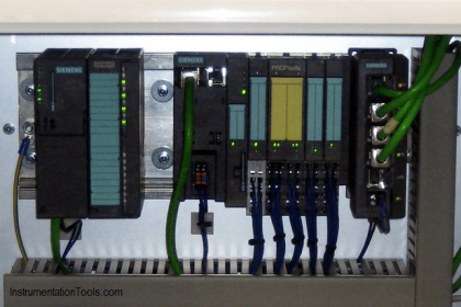
Troubleshooting PLCs can be started by checking the healthiness status of CPU, I/O Modules, Fuse Blow-out and different PLC Failure reasons including wiring, field transmitters healthiness status or transmitter configuration, check for any effect of induction voltage due to high voltage electrical cables etc. and many more reasons.

The below scenario is one of the example for PLC’s troubleshooting.

PLC Troubleshooting

PLC Problems Troubleshooting

Billy, an instrument technician works at a manufacturing facility, is on his break and He is just sitting down to eat some linguini when he gets a call that solvent flow into a mixing kettle is not reading right, and the rubber material looks like bad oatmeal. He drops his fork and makes his way to the drawing file, where he locates the proper drawing and uses it to wipe the noodles off his shirt. He then goes to the kettle and finds the solvent line and locates the flowmeter.

Then, He finds this differential pressure (dp) flowmeter is calibrated 0-–10 inches of water column (inwc) pressure across its diaphragm, which equates to a flow rate of 0-–100 pounds per hour (lb/hr) of solvent.

After getting approval from Operations and confirming the throttling valve is in manual mode and is closed, Billy disconnects the signal output cable from the transmitter and hooks the cable to a current source (a portable test device) to simulate the transmitter output signal. He then tries to inject a signal into the system.

The test device’s batteries are dead, so he has to go get more. With new batteries, he measures the injected signal with an ammeter, which reads 14.2 mA on a 4–-20 mA scale. He knows the resolution of the PLC input module is 12 bits, and that the operator reads the flow in PPH on a scale of 0-–100.

  1. What is the simulated pressure drop across the orifice in inches of water column? (Square root extraction is already accounted for in the transmitter.)
  2. What is the decimal integer value in the computer?
  3. What should the operator be seeing in pounds per hour?

The solutions follow, but first, try to solve it yourself.

First, Billy adjusts the analog value to account for the live-zero offset: 14.2 mA reading at the meter, minus the 4.0 mA offset, equals 10.2 mA. He knows he has a live span of 16 mA (20-4=16), and this span equates to 0–-10 inwc at the dp transmitter and 0-–100 PPH at the HMI.

Once the relative ranges are known, percentage of scale can be used to equate the values:

  1. The inwc value is (10.2 mA/16 mA) x 10 inwc = 6.375 inwc.

Then, Billy decides to check the PLC to make sure it is operating correctly. He knows the PLC has 12-bit analog input resolution, making the valid range of the PLC integer 0 to 4095 (2^12 = 4095). He uses a percentage-of-scale relationship to determine the proper integer value:

  1. The integer value should be: (10.2 mA/16 mA) x 4095 counts = 2611 counts.

Billy confirms the PLC is reading 2611 by checking the integer value in the PLC memory. He then checks the PLC program to make sure the integer is being moved to the proper memory location so it can be uploaded to the HMI.

He finds it is being moved to address 40021, which is in a data array that is being placed on the network. Further, the blinking light on the interface module confirms that the network is functioning.

So, he reasons, if a problem exists, it must be in the HMI. Billy goes to the control room and views the screen. He calculates the value he expects to see using the percentage-of-scale technique:

  1. The PPH value is (10.2mA/16mA) x 100 PPH = 63.75 PPH, or
  2. The PPH value is (2611 counts/4095 counts) x 100 PPH = 63.75 PPH

But the screen is reading 54.2 PPH. Billy takes the HMI system into development mode and checks the tag file for the configuration of that tag.

He finds the value animation being displayed for FT1001 = (13$40021/4095) x 85, where 13$40021 is the memory location of the PLC-stored integer value. He remembers the flow data array location in the PLC was address 40021, and the PLC was at network node 13.

But the proper scaling of the displayed value should be 0-–100, not 0-–85. Billy mentions his finding to the operator, who informs him that the transmitter, which was broken yesterday, was changed out last shift.

Billy surmises the technician changed everything but forgot to modify the HMI screen. Then, He changes the 85 to 100, recompiles the HMI program, and re-launches the application.

He confirms the displayed value equals the expected 63.75 PPH value. He removes his test equipment from the circuit and reconnects the wiring to the transmitter, but forgets to turn off the current source (which ensures the batteries will be dead next time), informs Operations that the problem is resolved, and returns to his linguini.

If you liked this article, then please subscribe to our YouTube Channel for PLC and SCADA video tutorials.

You can also follow us on Facebook and Twitter to receive daily updates.

Read Next:

PLC Reads from Field Transmitters

Mis-conceptions of PLC Ladder Logic

PLC Example with Switches

Motor Trip Logic using PLC

PLC Analog Input Scaling

Don't Miss Our Updates
Be the first to get exclusive content straight to your email.
We promise not to spam you. You can unsubscribe at any time.
Invalid email address
You've successfully subscribed !
Difference Between Wifi and Industrial Wireless
Why Are Charcoal and Salt Added to an Earthing Pit?
Basic Conveyor System for Product Handling in Omron PLC
PLC Example on Manufacturing Line Assembly
How to Prevent Ground Loops in Analog Circuits?
Share This Article
Facebook Whatsapp Whatsapp LinkedIn Copy Link
Share
3 Comments
  • Gabriel Tsali says:
    January 28, 2017 at 6:37 am

    I really enjoy your publications and it has help me learn a lot from.

    Reply
  • Sunny says:
    April 14, 2017 at 6:12 pm

    Pls how do we configure and calibrate a guided wave radar level transmitter.

    Reply
  • Balaji pathy says:
    January 12, 2020 at 5:35 pm

    its great sir, information into the story

    Reply

Leave a Reply Cancel reply

Your email address will not be published. Required fields are marked *

Stay Connected

128.3kFollowersLike
69.1kFollowersFollow
208kSubscribersSubscribe
38kFollowersFollow

Categories

Recent Comments

  • Guifty Shimica on Top Non-PLC Certification Courses for Automation Professionals
  • Guifty Shimica on Top Non-PLC Certification Courses for Automation Professionals
  • MIHARITSOA Aina Sitraka on Top Non-PLC Certification Courses for Automation Professionals
  • Vaishnavi on Free Instrumentation Course for Trainee Engineers

Related Articles

PLC IO Examples

Quiz: Identifying I/O Examples in PLC Systems

Types of PLC Memory

Types of PLC Memory

input-output-relationships-of-transmitters

Input-Output Relationships of Transmitters

Convert Raw Counts to Engineering Units

Raw Counts to Engineering Units : Conversion Formula

TIA Portal MOVE Instruction

MOVE Instruction in PLC – What You Need to Know?

Siemens Simatic HMI

How to Design an Effective HMI? – Human Machine Interface

Data Handling Instructions in PLC Programming

Data Handling Instructions in PLC Programming

PLC Motor Logic with START, STOP, TEST Push buttons

PLC Motor Logic with START, STOP, TEST Push buttons

More Articles

Seven Segment Display Programming with Structured Text

Seven Segment Display Programming with Structured Text

Closed-tank-DP-Level-Transmitter-with-wet-leg-Zero-elevation-Calibration

Closed tank DP Level Transmitter with wet leg Zero elevation Calibration

What is Heat Pump Water Heater?

What is Heat Pump Water Heater?

Properties of Conducting Materials

Resistivity

Gate Valve Parts

What is Gate Valve ?

PLC IO Examples

Quiz: Identifying I/O Examples in PLC Systems

Vortex Flow Meter Principle

Vortex Flow meter Animation

DIN Valve Connectors

DIN Valve Connectors – Definition, Types

Follow US
All rights reserved. Reproduction in whole or in part without written permission is prohibited.
Welcome Back!

Sign in to your account

Username or Email Address
Password

Lost your password?