Learn the PLC logic example on multiple switches and motors with the ladder diagram.
This PLC logic example is prepared for the engineering students to learn and practice the ladder logic. The design of the same PLC program for industrial usage will be different.
PLC Logic Example
Problem Statement:
Design a PLC ladder logic for the following application.
There is a use of four toggle switches to control four motors.
If Switch 1 is ON, then Motor I will be ON.
If Switch 2 is ON, then Motor I and Motor II will be ON.
If Switch 3 is ON, then Motor I, Motor II, and Motor III will be ON.
If Switch 4 is ON, then Motor I, Motor II, Motor III, and Motor IV will be ON.
PLC Logic Video
We explained the above PLC example logic in the below video. Follow the step-by-step procedure prepared for the beginners.
Inputs of PLC
The list of the digital inputs for this PLC logic is mentioned below.
Switch 1: I0.0
Switch 2: I0.1
Switch 3: I0.2
Switch 4: I0.3
Outputs of PLC
The required digital outputs are listed below.
Motor 1: Q0.0
Motor 2: Q0.1
Motor 3: Q0.2
Motor 4: Q0.3
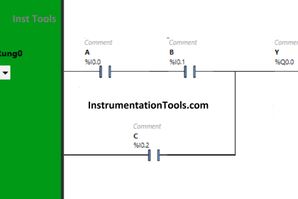
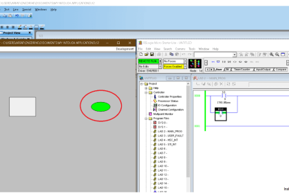
Multiple Switches and Motors Ladder Logic
Here is the PLC logic for the given problem statement.
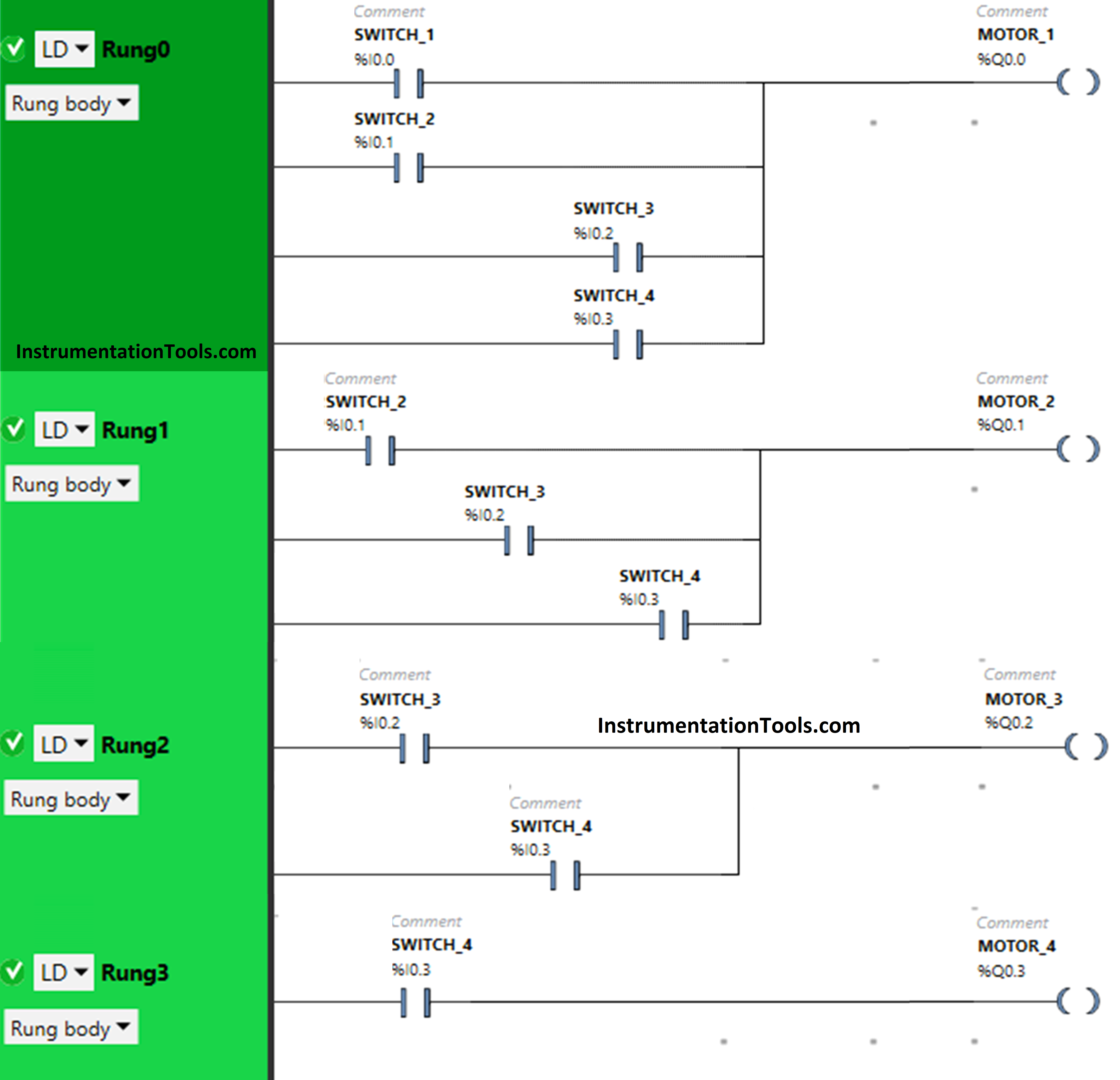
Program Explained
For this example, we used Schneider PLC software for programming.
In the above PLC program, we have used Normal Open Contact for Switch 1 (I0.0), Switch 2 (I0.1), Switch 3 (I0.2) and Switch 4 (I0.3)
Switch 1, Switch 2, Switch 3, and Switch 4 are connected in parallel for Motor 1, thus implementing OR logic gate.
For Motor 2, inputs switch 2, switch 3, and switch 4 are connected in parallel, thus implementing OR logic gate.
Switch 3 and switch 4 are implementing OR logic gate i.e., connected in parallel for Motor 3.
Only Switch 4 is connected to Motor 4.
For Motor 1 to be ON, either Switch 1 or Switch 2 or Switch 3 or Switch 4 should be ON.
To turn ON Motor 2, either Switch 2 or Switch 3 or Switch 4 should be ON.
When Switch 3 or Switch 4 is ON, then Motor 3 will turn ON.
Motor 4 will turn ON when Switch 4 is turned ON.
PLC Simulation Results
Next, we will see the PLC simulation results with different input switch ON and OFF combinations.
When Switch 1 is ON
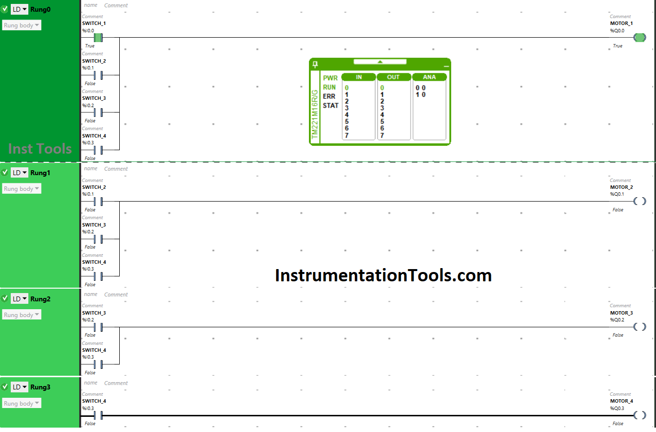
When the toggle switch 1 is turned ON, the current flows through it (here we are using the term “Current” in case of an electrical circuit, so here you can assume it as “Current” or simply call it as “Signal”).
As a result, Motor 1 gets ON. Other motors will remain OFF because Switch 1 is not connected to them.
When Switch 2 is ON
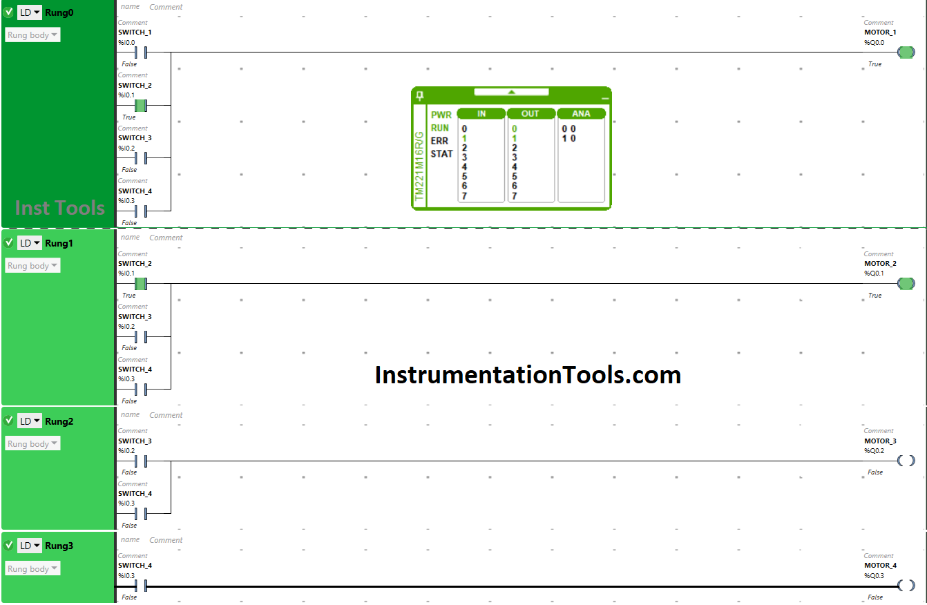
The current will flow through switch 2 when it is turned ON that will turn ON Motor 1 and Motor 2. It is so because switch 2 is connected to Motor 1 and Motor 2 only.
When Switch 3 is ON
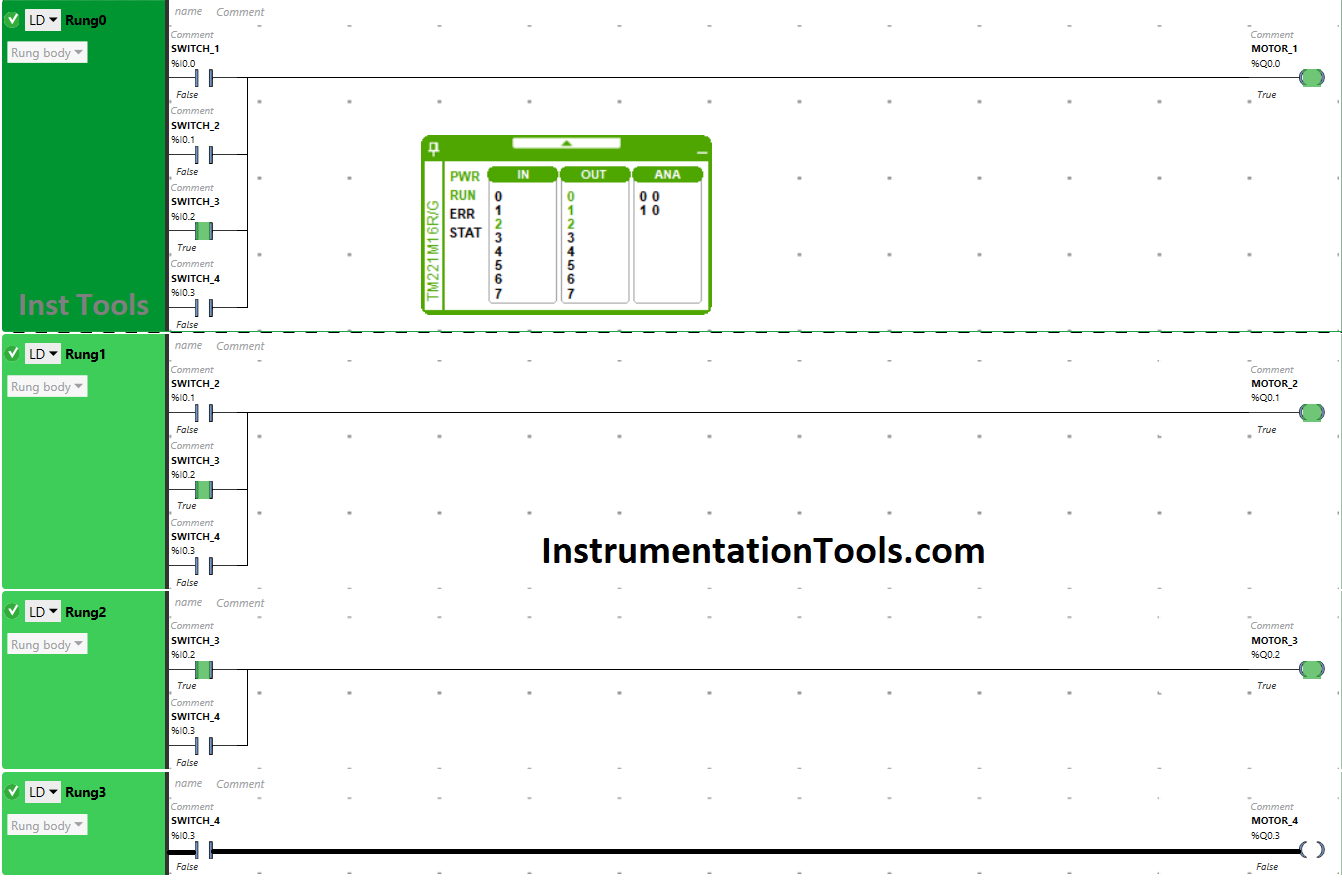
When Switch 3 is turned ON, the current flows through it that will turn ON three motors i.e., Motor 1, Motor 2 and Motor 3. The input switch 3 is connected to these outputs only. Motor 4 will remain OFF as Switch 3 is not connected to it.
When Switch 4 is ON
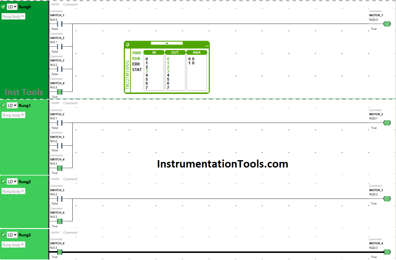
Switch 4 will turn ON all the motors when turned ON. Switch 4 is connected to all the motors, when turned ON, Motor 2, Motor 2, Motor 3 and Motor 4 will turn ON.
If you liked this article, then please subscribe to our YouTube Channel for PLC and SCADA video tutorials.
You can also follow us on Facebook and Twitter to receive daily updates.
Read Next:
- Siemens Control System (TDC)
- Electrical Diagram into PLC Program
- How to Choose a PLC for a Project?
- PLC Example to Control LEDs Via Switches
- Siemens Communication using I-Device