Inst ToolsInst ToolsInst Tools
  • Ask
  • Courses
  • Videos
  • Q & A
    • Interview
      • Instrumentation
      • Electronics
      • Electrical
      • Practical Questions
    • MCQ
      • Instrumentation MCQ
      • Electrical MCQ
      • Electronics MCQ
      • Control Systems MCQ
      • Analog Electronics MCQ
      • Digital Electronics MCQ
      • Power Electronics MCQ
      • Microprocessor MCQ
      • Multiple Choice Questions
  • EE
    • Electronics
      • Electronics Q & A
      • Electronic Basics
      • Electronic Devices & Circuits
      • Electronics Animation
      • Digital Electronics
    • Electrical
      • Electrical Basics
      • Electrical Q & A
      • Power Electronics
      • Electrical Machines
      • Electrical Animation
      • Power Systems
      • Switchgear & Protection
      • Transmission & Distribution
  • Measure
    • Control Valves
    • Calibration
    • Temperature
    • Pressure
    • Flow
    • Level
    • Analyzers
    • Switches
    • Vibration
    • Solenoid Valve
  • Control
    • PLC Tutorials
    • Control Systems
    • Safety Instrumented System (SIS)
    • Communication
    • Fire & Gas System
  • More
    • Design
    • Tools
    • Animation
    • Basics
    • Formulas
    • Standards
    • TextBooks
    • Common
    • Software
    • Excel Tools
    • Erection & Commissioning
    • Process Fundamentals
    • Videos
    • Books
Search
All rights reserved. Reproduction in whole or in part without written permission is prohibited.
Reading: Implement UDT in PLC Programming: User-Defined Data Type
Share
Notification Show More
Font ResizerAa
Inst ToolsInst Tools
Font ResizerAa
  • Courses
  • PLC Tutorials
  • Control Systems
Search
  • Ask
  • Courses
  • Videos
  • Q & A
    • Interview
    • MCQ
  • EE
    • Electronics
    • Electrical
  • Measure
    • Control Valves
    • Calibration
    • Temperature
    • Pressure
    • Flow
    • Level
    • Analyzers
    • Switches
    • Vibration
    • Solenoid Valve
  • Control
    • PLC Tutorials
    • Control Systems
    • Safety Instrumented System (SIS)
    • Communication
    • Fire & Gas System
  • More
    • Design
    • Tools
    • Animation
    • Basics
    • Formulas
    • Standards
    • TextBooks
    • Common
    • Software
    • Excel Tools
    • Erection & Commissioning
    • Process Fundamentals
    • Videos
    • Books
Follow US
All rights reserved. Reproduction in whole or in part without written permission is prohibited.
Inst Tools > Blog > PLC Tutorials > Implement UDT in PLC Programming: User-Defined Data Type

Implement UDT in PLC Programming: User-Defined Data Type

In this article, we will show one way to use UDT in PLC programming with an example (User-Defined Data Type).

Last updated: August 29, 2023 2:58 pm
Mahmoud Salama
PLC Tutorials
No Comments
Share
8 Min Read
SHARE

In the previous article, we talked about what a UDT is, how to create User-Defined Data Types (UDT), and the advantages of using UDTs in your project. In this article, we will show one way to use UDT in your PLC programming.

Contents
UDT in PLC ProgrammingOld Tank Simulator Function BlockNew tank simulation FB with UDT:Calling the new tank simulation FB:Conclusion

Contents:

  • Old tank simulator function block.
  • New tank simulation FB with UDT.
  • Calling the new tank simulation FB.
  • Adding a new tag to the UDT.
  • Conclusions.

UDT in PLC Programming

In our last few articles, we used the same tank simulator system to explain many concepts, like closed-loop control and PID controllers. In this article, we will use the same tank simulator to show how we can use the concept of UDTs in our programming.

Old Tank Simulator Function Block

In the old tank simulator system we defined some internal parameters for the sake of reusing the function block as many times as we wanted. See picture 1.

UDT in the PLC Programming

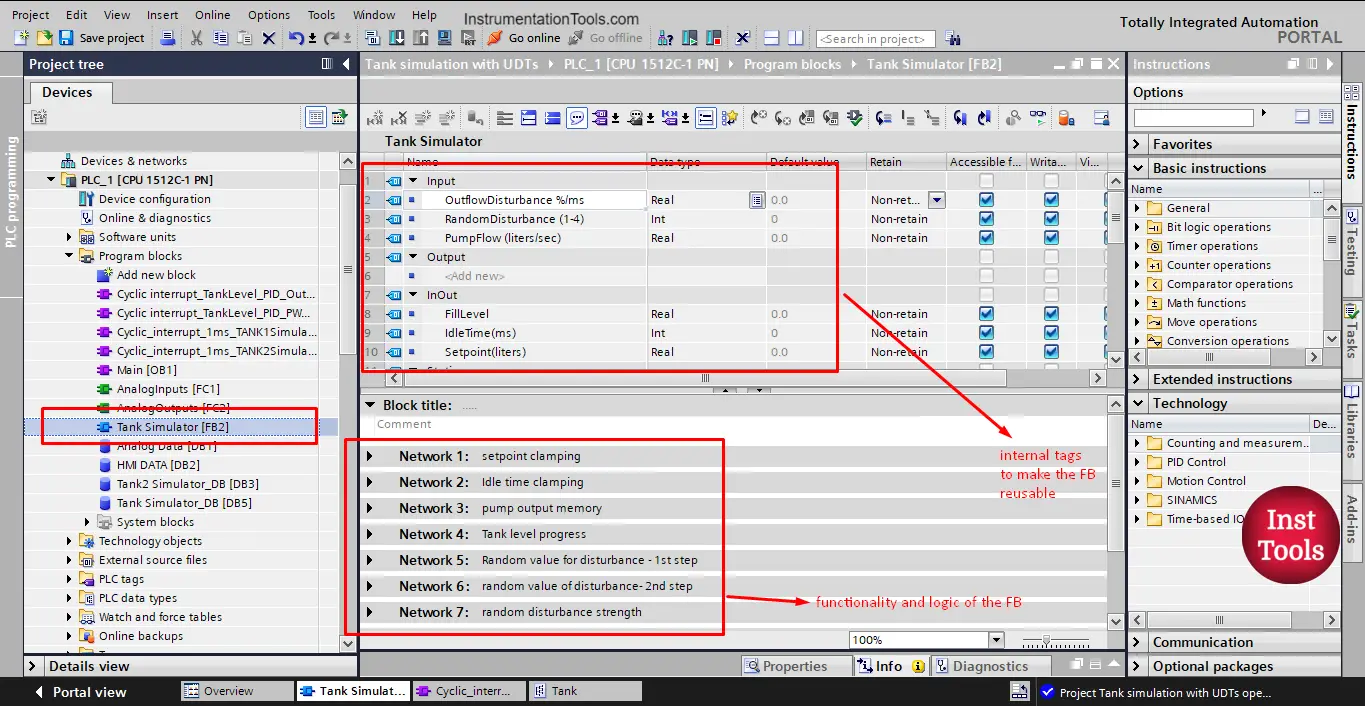
picture 1. Tank simulator FB.

As you see from the picture, in the function block interface we defined some inputs and some InOuts, these parameters should be provided when the FB is called.

For example, if we called the FB to simulate tank 1 and called it again to represent tank 2, we need to provide the parameters for each tank to the related called function block. See picture 2.

Understanding user-defined data type

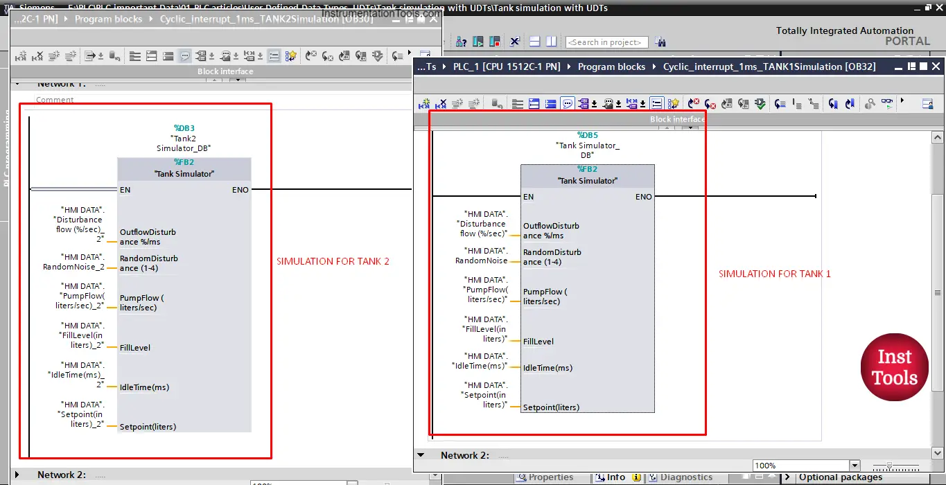
picture 2. Simulation of tank 1 and tank 2.

You can see that for each FB call, we have to assign the related tags. For tank 1 simulation we should assign tags of tank 1 to the called FB. And the same for the tank 2 simulation.

New tank simulation FB with UDT:

Now, we want to use the UDT “Tank” that we defined in the last article to simulate our tanks. We will create a new simulation function block. See picture 3.

Define PLC data types (UDTs) in STEP 7

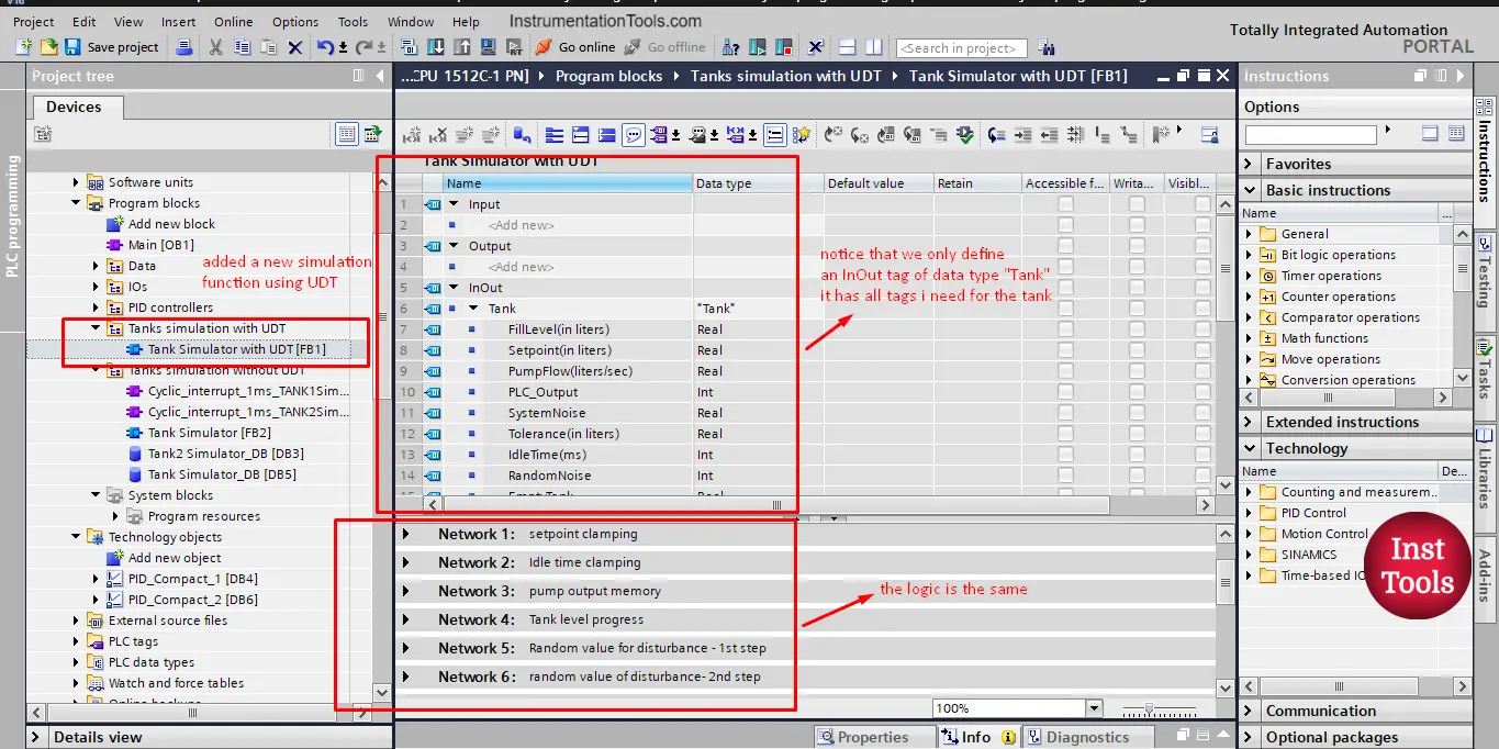
picture 3. Add new tank simulation FB.

The new simulation function block has the same logic as the old FB, but in this simulation function, we will use the defined UDT “Tank” as an InOut internal tag as you see from the picture.

So instead of having your function block parameters declared in the different areas of the FB interface, now it will be just one tag that carries all needed information of the tank.

Calling the new tank simulation FB:

To call the new simulation function, we choose to call it inside a cyclic interrupt OB, to make sure the execution of the function block is not affected by the main logic OB1 cycle time as we explained with PIDs.

So we need to first create a new cyclic interrupt OB. See picture 4.

Explaining User-Defined Data Types for PLC Programming

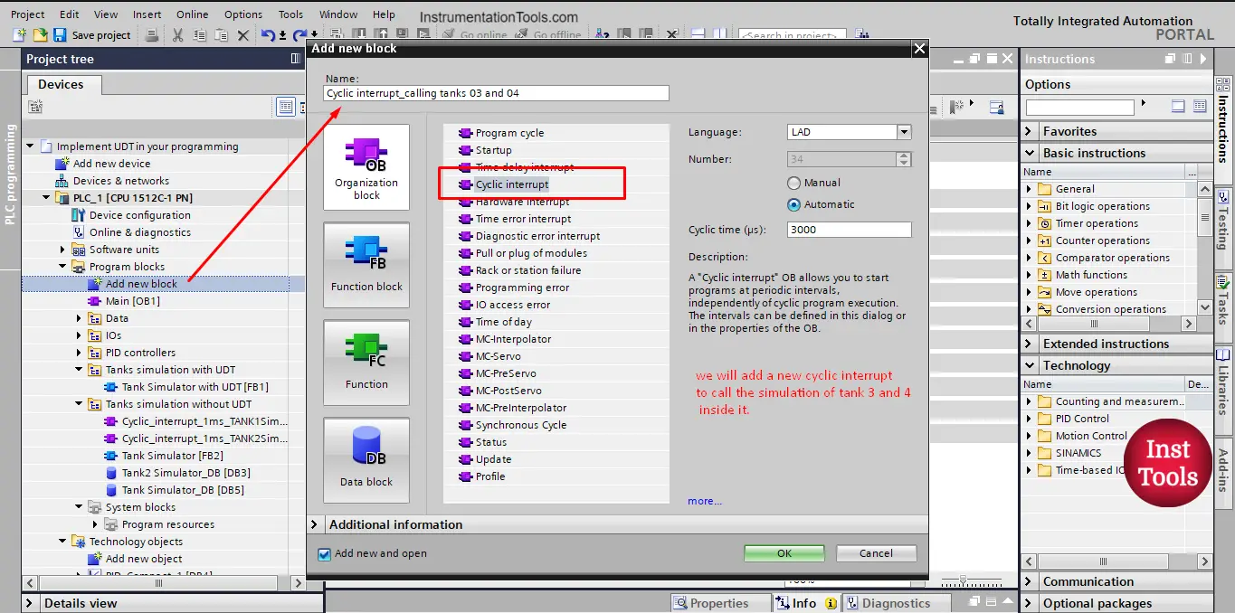
picture 4. Adding a cyclic interrupt to call tanks 3 and 4.

You can choose the cyclic time as you see fit, in our case we set it to 3000 microseconds or 3 milliseconds.

Now, you can drag and drop your “Tank Simulator with UDT” FB into your cyclic interrupt to call the FB. A call option window will appear, giving the FB data instance whatever name you like. See picture 5.

How Do You Program User-Defined Data Types

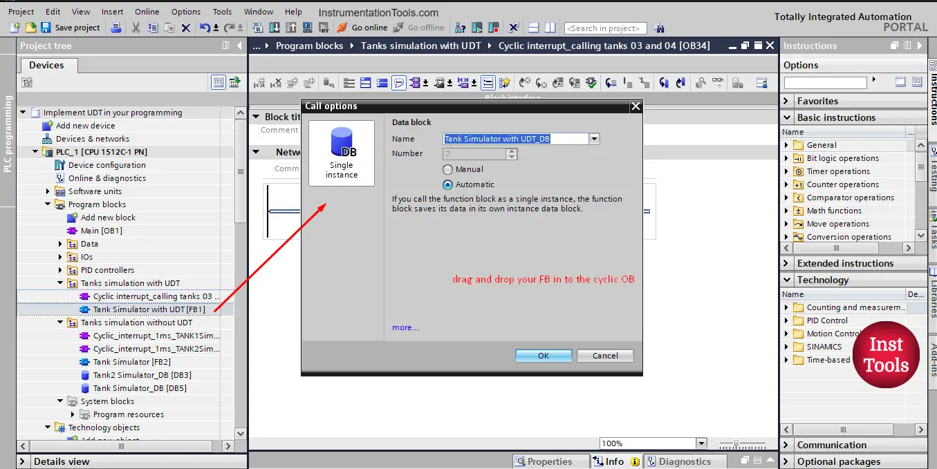
Picture 5. Call your FB.

After calling the FB, you know need to assign the parameters related to the tank you want to simulate. See picture 6.

User Defined Datatype UDT Usage Examples

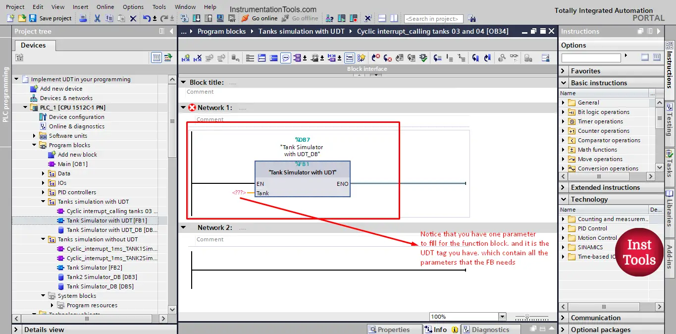
picture 6. Assign tank parameters to the FB call.

Notice that you have only one parameter to fill for the function block. And it is the UDT tag that you have created. Which already contain all tank parameters that the function block needs.

We want to simulate Tank_03 so we will assign the tag to the FB call. See picture 7.

Creating a user-defined type (UDT)

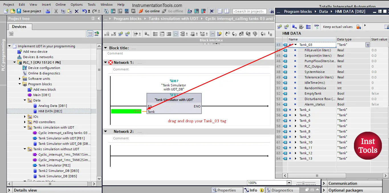
picture 7. Drag and drop your tag.

The function block call for tank 3 looks simpler than the call of tank 1 with the old simulator FB without UDTs. See picture 8.

udt in siemens plc

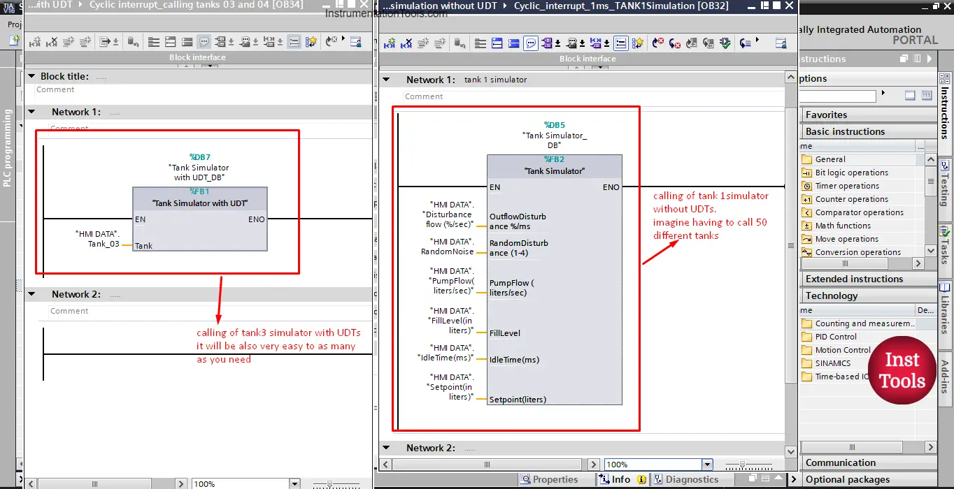
picture 8. Tank 1 and tank 3 calling differences.

Can you see the difference between the two tanks calls? You have to provide all the parameters of the function block in the case of without UDTs. imagine if you have to simulate 50 tanks with this simulator. It will be very boring and time-consuming to assign all these parameters, not to mention, to declare them first for each tank.

But in the case of the simulator with UDTs, you can call as many as you want and it won’t take much time or effort. See picture 9.

Siemens TIA Portal PLC tutorial - User Defined Data Types

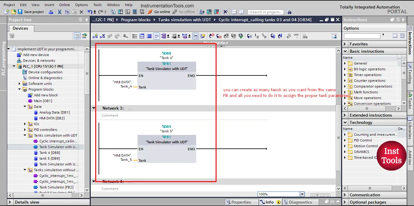
picture 9. Calling many other tanks.

Now, imagine that you have to add a new variable to your simulation. For example, you want to add an Outflow Warning signal. With the old simulator function block without UDT, This will mean that you have to declare this new tag for each tank and you have to add it one by one to each time you call a tank.

But with UDTs, you only need to update the UDT you created and add the new tag you want. See picture 10.

An Introduction to Siemens UDT

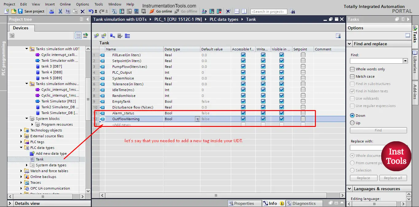
picture 10. Adding a new tag to the UDT.

When you make any changes to the UDT, you won’t even need to update the function call. Because the call parameter is the same, the changes were made inside the parameter itself. See picture 11.

How to use User-Defined Types

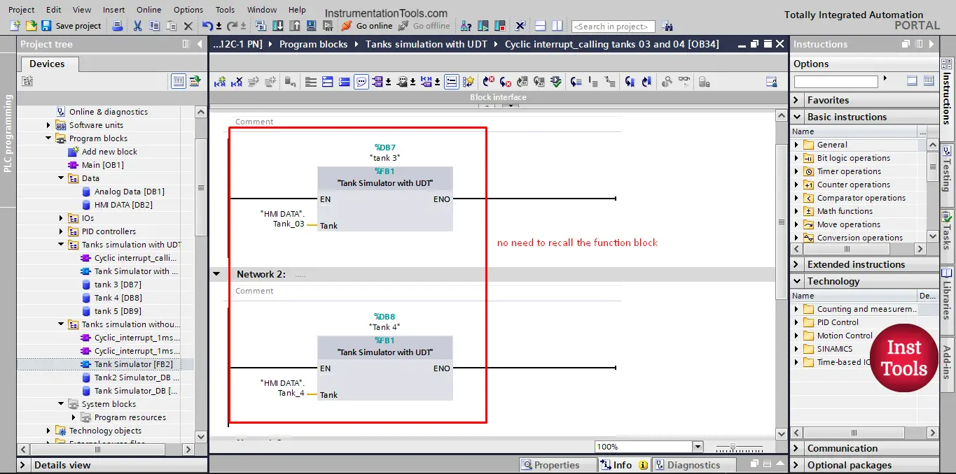
picture 11. No need to recall the FB.

However, you still need to recompile your PLC project or at least the data block so the changes to the UDT can be updated. See picture 12.

PLC Programming With UDT Structures

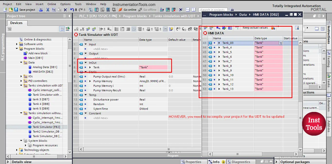
picture 12. Recompile to update the changes to the UDT.

After you compile all the changes to the UDT will be automatically updated to all declared tags of this UDT. See picture 13.

UDT in siemens plc example

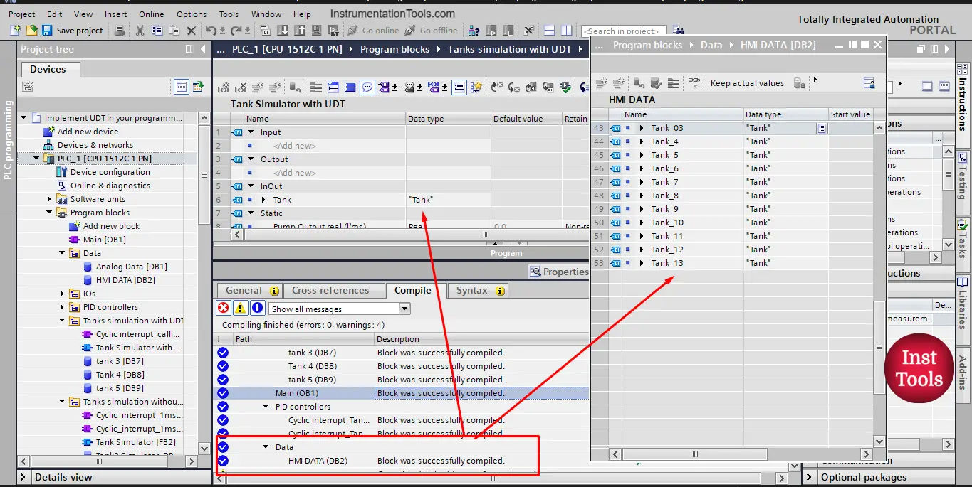
picture 13. All tags are now updated.

Download: Siemens UDT Programming

Conclusion

  • You can use the UDTs in your project to make your programming faster and easier to follow.
  • Using UDTs will also make it easier to make changes to your functions and function blocks.

If you liked this article, then please subscribe to our YouTube Channel for Instrumentation, Electrical, PLC, and SCADA video tutorials.

You can also follow us on Facebook and Twitter to receive daily updates.

Read Next:

  • Advanced PLC Conveyor Logic
  • What are AI, AO, DI, and DO?
  • Power Supply Sizing for Systems
  • How to Read the PLC Datasheet?
  • OB100 Start-up Organization Block
Don't Miss Our Updates
Be the first to get exclusive content straight to your email.
We promise not to spam you. You can unsubscribe at any time.
Invalid email address
You've successfully subscribed !
Proper Earthing Practices Used for PLC Control Panel
Top Free PLC Software
AENT Module in Rockwell PLC – Remote IO Adapter
Electrical Drives – Modes, Types, Speed Control Applications
How-to do Security of SCADA Systems?
Share This Article
Facebook Whatsapp Whatsapp LinkedIn Copy Link
Share
Leave a Comment

Leave a Reply Cancel reply

Your email address will not be published. Required fields are marked *

Stay Connected

128.3kFollowersLike
69.1kFollowersFollow
208kSubscribersSubscribe
38kFollowersFollow

Categories

Recent Comments

  • Kamli on Top Free PLC Software
  • Guifty Shimica on Top Non-PLC Certification Courses for Automation Professionals
  • Guifty Shimica on Top Non-PLC Certification Courses for Automation Professionals
  • MIHARITSOA Aina Sitraka on Top Non-PLC Certification Courses for Automation Professionals

Related Articles

Example Ladder Logic Diagram

What is Relay Logic ?

Sequencer Output in PLC

PLC Sequencer Instruction with Example

Water Fountain Control Logic

Water Fountain Control Logic – PLC Exercises and Solutions

DCS Alarm and Setpoint

Setpoints and Alarms in Control System

Latching and Unlatching in PLC Programming for Beginners

Latching and Unlatching in PLC Programming Example

Omron PLC Mixing System

Mixing Program with Timers and Counters in Omron PLC

Timer STL Programming

Timers using Statement List (STL) PLC Programming

Control Methods in Servo Motor Drives

Various Control Methods in Servo Motor Drives

More Articles

30% Feed Control Valve

Purpose of 100% and 30% Feed Control Valves in a Power Plant

Densitometers Principle

Vibrating Tube Densitometers Working Principle

Gauge Display Scale

How to Read Gauge Analog Scales

Boiler Feed Water Treatment

Boiler Feed Water Treatment

Time Response Analysis

Design Considerations for Higher Order Systems

Electrical Machines Questions and Answers

DC Machines Excitation Quiz

RC snubber circuits

How Snubber Circuit works ?

Difference Between RCCB and MCCB

Difference Between RCCB and MCCB

Follow US
All rights reserved. Reproduction in whole or in part without written permission is prohibited.
Welcome Back!

Sign in to your account

Username or Email Address
Password

Lost your password?