Inst ToolsInst ToolsInst Tools
  • Ask
  • Courses
  • Videos
  • Q & A
    • Interview
      • Instrumentation
      • Electronics
      • Electrical
      • Practical Questions
    • MCQ
      • Instrumentation MCQ
      • Electrical MCQ
      • Electronics MCQ
      • Control Systems MCQ
      • Analog Electronics MCQ
      • Digital Electronics MCQ
      • Power Electronics MCQ
      • Microprocessor MCQ
      • Multiple Choice Questions
  • EE
    • Electronics
      • Electronics Q & A
      • Electronic Basics
      • Electronic Devices & Circuits
      • Electronics Animation
      • Digital Electronics
    • Electrical
      • Electrical Basics
      • Electrical Q & A
      • Power Electronics
      • Electrical Machines
      • Electrical Animation
      • Power Systems
      • Switchgear & Protection
      • Transmission & Distribution
  • Measure
    • Control Valves
    • Calibration
    • Temperature
    • Pressure
    • Flow
    • Level
    • Analyzers
    • Switches
    • Vibration
    • Solenoid Valve
  • Control
    • PLC Tutorials
    • Control Systems
    • Safety Instrumented System (SIS)
    • Communication
    • Fire & Gas System
  • More
    • Design
    • Tools
    • Animation
    • Basics
    • Formulas
    • Standards
    • TextBooks
    • Common
    • Software
    • Excel Tools
    • Erection & Commissioning
    • Process Fundamentals
    • Videos
    • Books
Search
All rights reserved. Reproduction in whole or in part without written permission is prohibited.
Reading: Create User-Defined Data Types and Function Blocks in Studio 5000
Share
Notification Show More
Font ResizerAa
Inst ToolsInst Tools
Font ResizerAa
  • Courses
  • PLC Tutorials
  • Control Systems
Search
  • Ask
  • Courses
  • Videos
  • Q & A
    • Interview
    • MCQ
  • EE
    • Electronics
    • Electrical
  • Measure
    • Control Valves
    • Calibration
    • Temperature
    • Pressure
    • Flow
    • Level
    • Analyzers
    • Switches
    • Vibration
    • Solenoid Valve
  • Control
    • PLC Tutorials
    • Control Systems
    • Safety Instrumented System (SIS)
    • Communication
    • Fire & Gas System
  • More
    • Design
    • Tools
    • Animation
    • Basics
    • Formulas
    • Standards
    • TextBooks
    • Common
    • Software
    • Excel Tools
    • Erection & Commissioning
    • Process Fundamentals
    • Videos
    • Books
Follow US
All rights reserved. Reproduction in whole or in part without written permission is prohibited.
Inst Tools > Blog > PLC Tutorials > Create User-Defined Data Types and Function Blocks in Studio 5000

Create User-Defined Data Types and Function Blocks in Studio 5000

In this post, we will learn how to create user-defined data types and function blocks in Studio 5000 software.

Last updated: September 28, 2022 4:07 pm
Viral Nagda
PLC Tutorials
No Comments
Share
7 Min Read
SHARE

In this post, we will see how to create user-defined data types and function blocks in Studio 5000 software.

Contents
User-Defined Data Types in Studio 5000Add-On Instructions (User Defined Function Blocks)Create the ProgramRead Next:

As we know, user-derived data types and function blocks play a very important role in PLC software. A programmer finds it easier to develop the logic faster and more efficiently if there is a repeated type of logic in the whole program.

That means, suppose there are 10 motors and each motor should start by pressing the start button and stop by pressing the stop button.

Instead of writing the same logic for all the 10 motors every time, he can just create his own library or data type which will contain a common logic; and it can be used in multiple instances within the whole logic.

User-defined types are available in almost every PLC software. In this post, we will see one such software of Rockwell Automation – Studio 5000. This software is used to program Rockwell PLCs like Compact Logix, Control Logix, and Flex Logix series. It is a very high-end one and has many advanced features available to make the task easier for the programmer.

User-Defined Data Types in Studio 5000

So, what is a data type? A Boolean, integer, real, etc.; the terms which a programmer has faced while creating a variable is called data type. It defines the type of data or variable used.

User-defined data type means a programmer can manually create his own data type and give it any name according to his convenience. Refer to the below steps to create a user-defined data type in Studio 5000.

As shown in the image, expand the assets category. Expand the data types category and in that, right-click the user-defined option as shown to create a new data type.
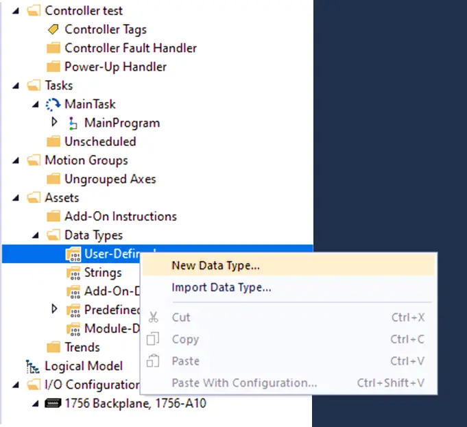
User Defined Data Types

On clicking it, the following window will appear. Here, you have to click add a member as shown; to add variables of the data type you want; and give a name for the data type.

For example, as discussed earlier, two variables have been created – start and stop. Both these variables are of Boolean type.

Clicking Ok will create a data type of the name motor. Now, understand the logic. If you are creating a variable named M1 of type Boolean; you can create it as type motor also.

This means, if created, then the M1 variable will have two members accordingly – M1. Start and M1. Stop.
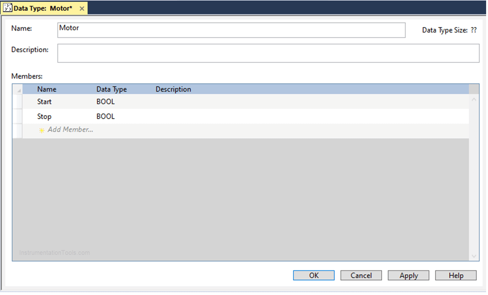
Create User-Defined Data Types in Studio 5000

Add-On Instructions (User Defined Function Blocks)

A user-defined function block is a library created by the programmer himself. For example, as the timer is a predefined library that comes inbuilt with the PLC software, a user-defined library is the one that will be customized by the programmer according to his requirements accordingly.

Refer to the below steps to create a user-defined function block in Studio 5000.

As shown in the image, expand the assets category. Right-click the Add-on Instructions option as shown to create a new function block.
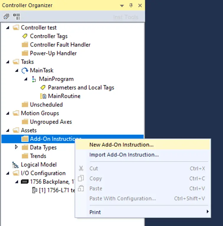
Add-On Instructions in Studio 5000

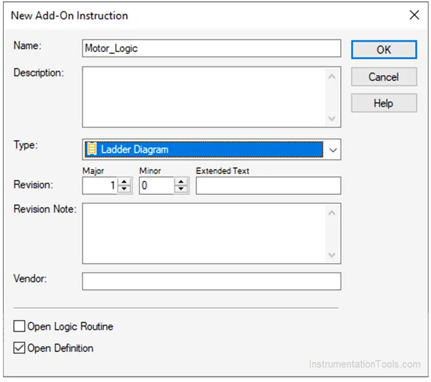
On clicking it, the following window will appear. Name the library according to you and define the programming language.

Here, I have named the function block as Motor_Logic and chosen the ladder diagram as the programming language.
Motor Logic in Studio 5000

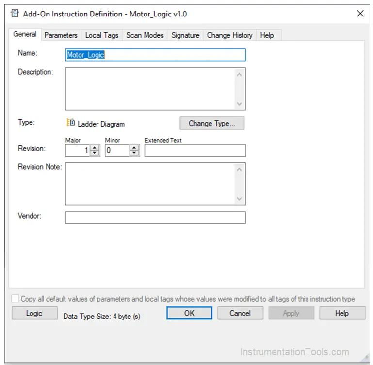
On clicking Ok, the following window will appear.

Just click Ok.
chosen ladder diagram as programming language

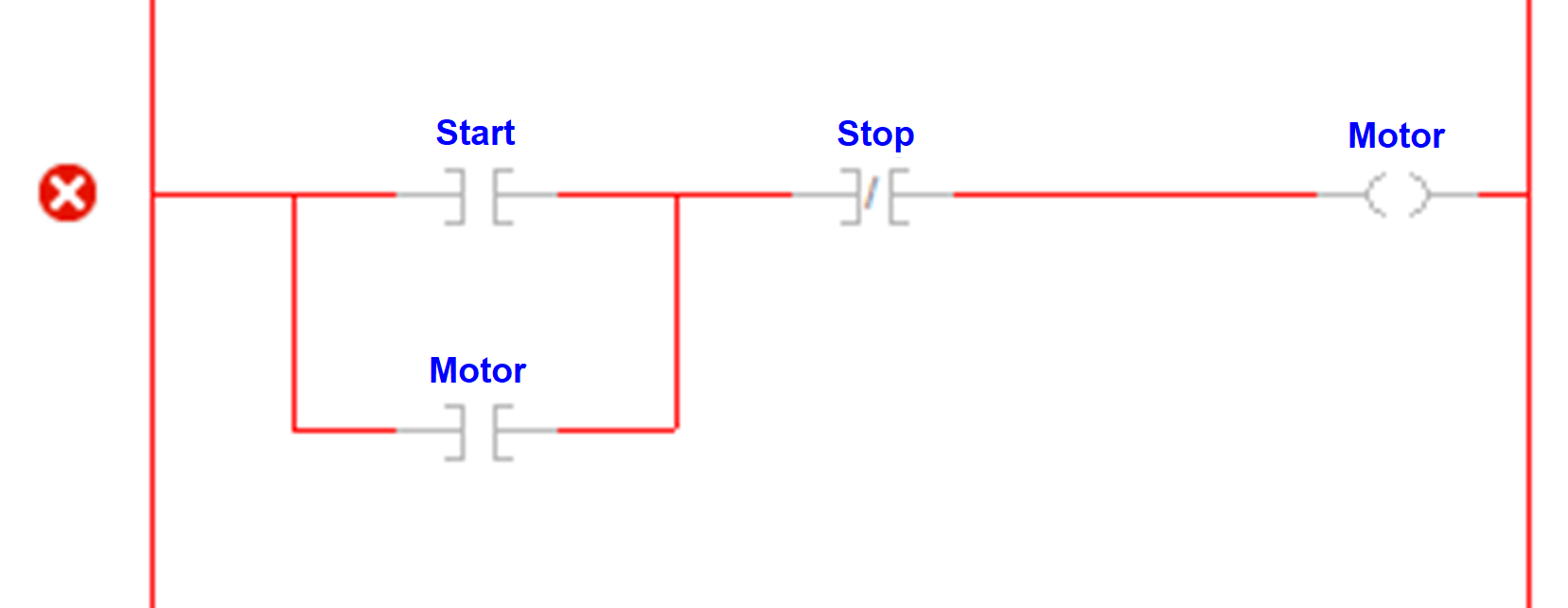
Develop the logic according to you, as shown in the figure. When you create, you will be asked to create variables first; if undeclared.

As shown, I have not created variables initially; that is why it is showing as the red cross mark on the left side. This is because the rung has errors.

Here, create start and stop as input parameters; and create motor as output variable.
Studio 5000 Ladder Program

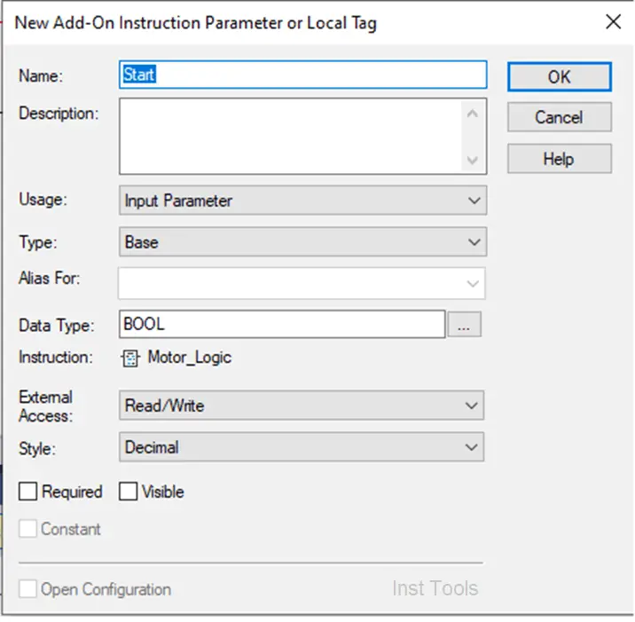
When you right-click any undeclared or undefined variable to create a new parameter, the following popup will appear.

Select the Input parameter for the input variable and the output parameter for the output variable. Choose the data type and click ok.

The variable will be created.
User Defined Function Blocks in PLC

When the whole rung is now clear without any error, it will appear as follows:
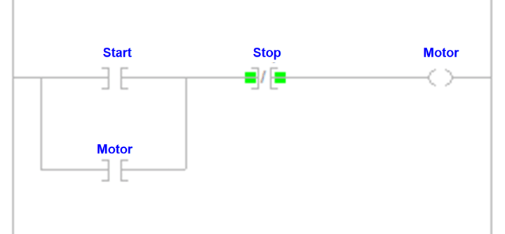
Without any Error in PLC Logic

Create the Program

Now that your data type and function block is created, you can use them in your main program. Refer to the below image.

In the add-on option, choose Motor_Logic library.

An undeclared library will be added. Type M1_Logic and create it with type – Motor_Library.
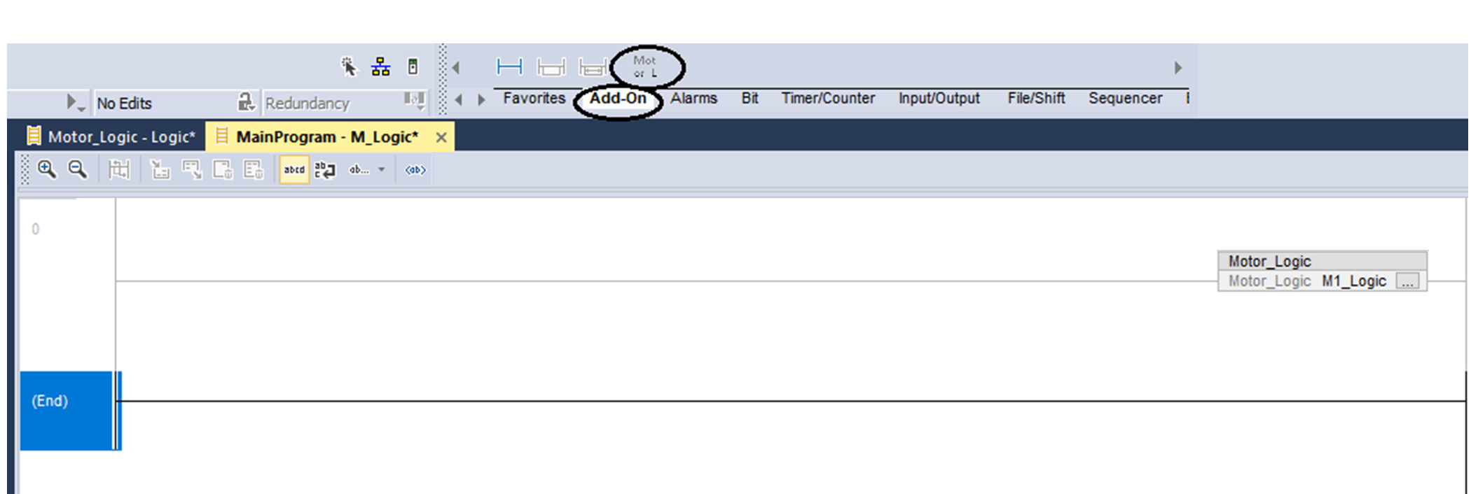
Motor Function Block

Right-click the newly created library and select open instruction definition.

The following window will appear. Tick Req (Required) option for the variables required to be pinned in the library outside, for linking external variables to it.
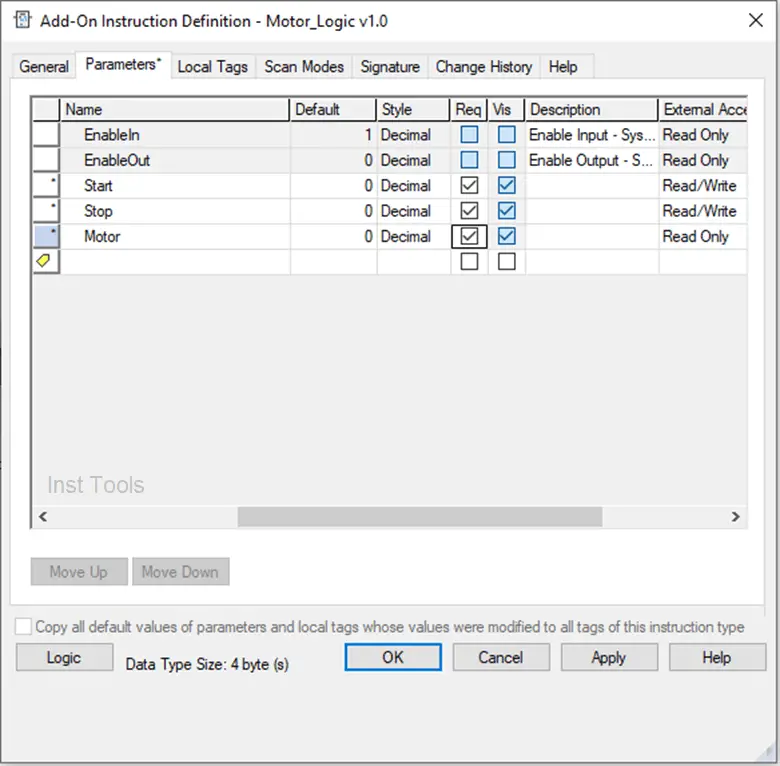
open instruction definition

Click ok and you can now link external variables in your library pins; as shown in the figure.

Now, I have created two instances of the motor library and created two variables (M1 and M2) of data type – motor. And, it has been linked to start and stop pins of the library.

That means, whenever the variable – M1. Start turns on, the motor will turn on according to the logic written inside before; and stop when the variable – M1. Stop turns on.

The same logic will work for motor 2.
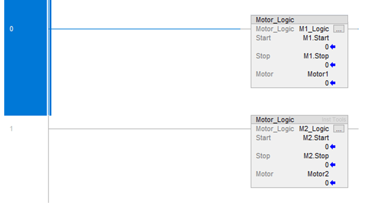
Motor Library in Studio 5000 PLC

In this way, we saw how to create user-defined function blocks and libraries in this software.

If you liked this article, then please subscribe to our YouTube Channel for Electrical, Electronics, Instrumentation, PLC, and SCADA video tutorials.

You can also follow us on Facebook and Twitter to receive daily updates.

Read Next:

  • UPS Working Principle
  • Wiring in a PLC Control Panel
  • Why 24 Volts DC Power Supply?
  • Interposing Relay Panel Wiring
  • Types of Cables in Industries
Don't Miss Our Updates
Be the first to get exclusive content straight to your email.
We promise not to spam you. You can unsubscribe at any time.
Invalid email address
You've successfully subscribed !
PLC Program to Heat and Bend Glass Tubes
How to Retrieve PLC Project From Memory Card?
Motor ON OFF Logic in PLC
Types of Digital Outputs in PLC
PLC Program for Fish Feeding System
Share This Article
Facebook Whatsapp Whatsapp LinkedIn Copy Link
Share
Leave a Comment

Leave a Reply Cancel reply

Your email address will not be published. Required fields are marked *

Stay Connected

128.3kFollowersLike
69.1kFollowersFollow
208kSubscribersSubscribe
38kFollowersFollow

Categories

Recent Comments

  • Kamli on Top Free PLC Software
  • Guifty Shimica on Top Non-PLC Certification Courses for Automation Professionals
  • Guifty Shimica on Top Non-PLC Certification Courses for Automation Professionals
  • MIHARITSOA Aina Sitraka on Top Non-PLC Certification Courses for Automation Professionals

Related Articles

Introduction to SCADA

Types of Script in Intouch Scada

Types of Script in Intouch Scada

Offline UPS

UPS Working Principle and Types – Offline and Online UPS Systems

Masking in PLC

What is Masking in PLC?

Programmable Logic Controller Quiz

Programmable Logic Controller Quiz

Unspecified CPU in Tia Portal

How to Add Unspecified CPU in Tia Portal?

Omron CX programmer shift register

The Concept of Shift Register in Omron PLC with Example

Allen Bradley RSLogix 500 PLC Programming

More Articles

Mixing Process with Valve Control

PLC Mixing Process with Adjustable Timer and Valve Control

PLC Control for Baking Machines Logic

PLC Programming for Baking with Auto and Manual Modes

Digital Electronics Multiple Choice Questions

Parallel Adder and Subtractor Objective Questions

Full-Controlled Rectifier Working Principle

Single-Phase Mid-Point Converter – Bridge Rectifier with Center Tap

Ball Valve Pictures

How Ball Valves Work ?

SC connector

What is a Network Connector? – Types of Connectors

NIST Traceability

NIST Traceability

In this article, we will learn the difference between Machine Expert Basic and Machine Expert software in Schneider PLC.

Difference between Machine Expert Basic and Machine Expert – Schneider PLC

Follow US
All rights reserved. Reproduction in whole or in part without written permission is prohibited.
Welcome Back!

Sign in to your account

Username or Email Address
Password

Lost your password?