In this article, you will learn the DP type flow transmitter preventive maintenance (PM) activity and calibration procedure in the field.
Before starting the maintenance activity we have to follow the below steps.
First, you have to take the proper work permit.
Tools List
Gather the required tools and instruments for the PM job.
- Digital Multimeter
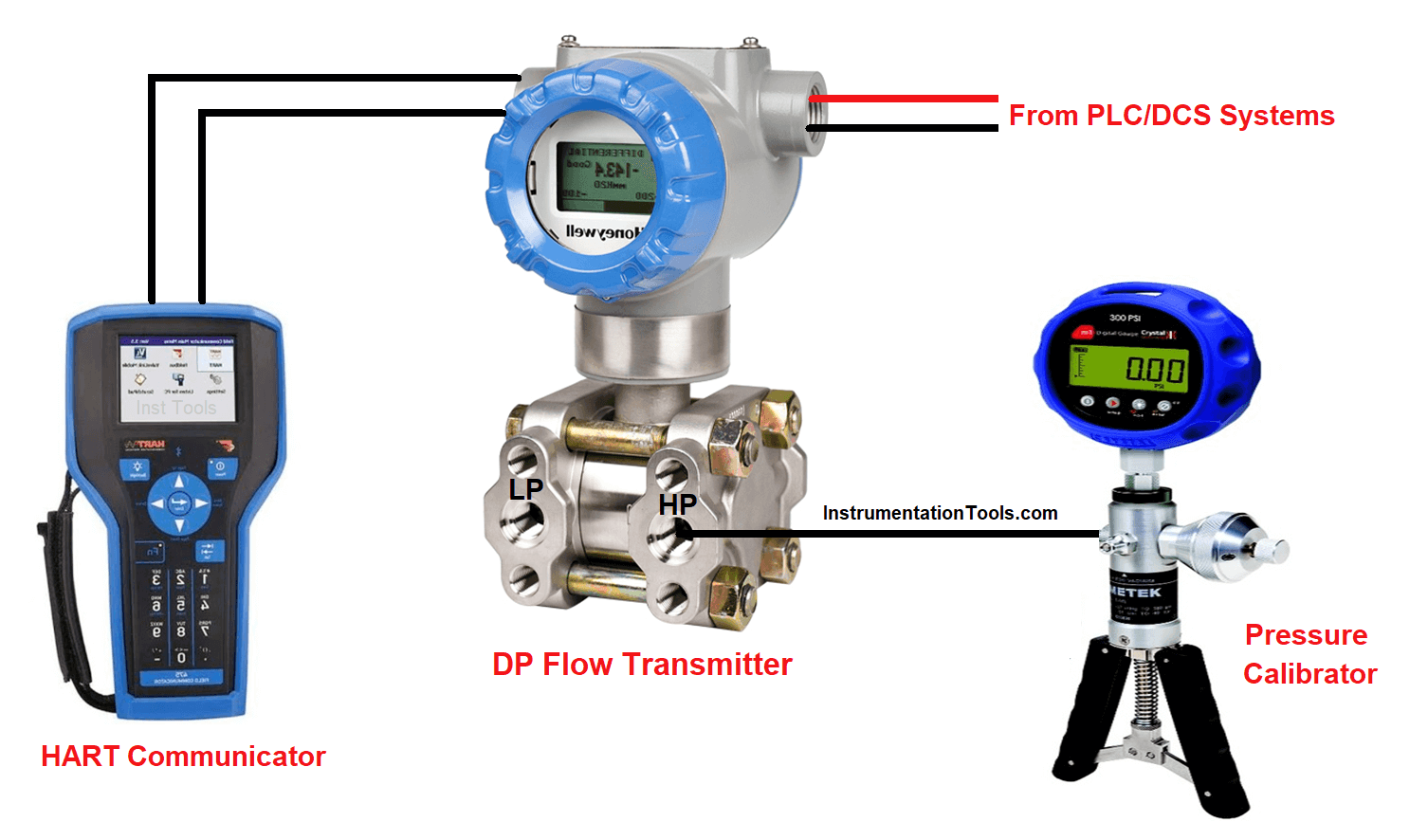
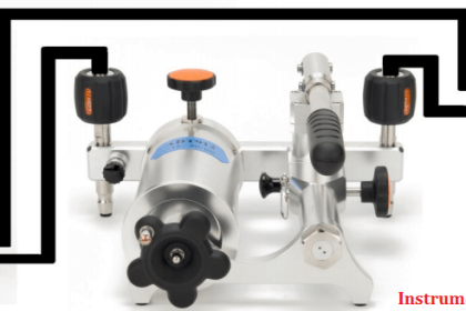
- Pressure Calibrator
- HART 375/475 Communicator
- Other Tools
We must make sure that the required instruments must have valid calibration before using them for our PM job. Make sure the instruments are properly charged (like the HART communicator).
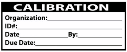
We have to use a calibration sticker at the end of our PM activity. So get one new label, which is shown in the below image.
We have to use proper PPE for the job. So check all the required PPE available or not before starting the job.
Check the datasheet of the DP type flow transmitter and note down the ranges. Here we need two range values. One is in mmH2O which is the DP range and the second one is the actual flow range which is in m3/hr range (or any other units)
Take out the range of the transmitter from the data sheet of the DP type Flow transmitter. Here you will see two ranges. One is in mmH2O which is the DP range. Another is the m3/hr range which is the output flow range.
DP type Flow Transmitter Preventive Maintenance
- Take appropriate work permit and take necessary approvals.
- Bypass the interlock if the DP type Flow transmitter is having any interlocks (Always take a bypass approval from operations and fill the Interlock Bypass Form).
- Instrument engineer should check whether the square root function is present in the field transmitter or in the PLC or DCS system.
- Verify the flow transmitter tag number. You should always ask the value shown by DP type Flow transmitter on the DCS/SCADA/PLC and confirm the value in field. This is a double confirmation for identifying the proper tag. (optional)
- Note down the value shown by DP type Flow transmitter before starting the PM job.
- Ask the operation engineer to arrange for the isolation of the DP type Flow transmitter through a process isolation valve (if required).
- Open the back cover of the DP type Flow transmitter and check the connections.
- Note down all the cable connections. So that it will be easy to restore the connections after completing the PM.
- Check the input supply voltage.
- Connect HART 375/475 communicator with the DP type Flow transmitter.
- Open the equalization valve on the manifold and check the zero reading of the DP type Flow transmitter.
- Now properly drain the fluid (for hazardous service close drain is required).
- Connect the pressure calibrator or pressure source to the HP tapping point of the flow transmitter.
- As per the range of the DP type Flow transmitter datasheet, set the required pressure on the pressure calibrator and feed it to the DP type Flow transmitter.
- Now apply respective pressure and note down the output of the transmitter (confirm in field display as well as from control room DCS/SCADA/PLC).
- Repeat the above step for different calibration points. The general rule is to apply the input pressure in terms of 0%, 25%, 50%, 75%, and 100%.
- We have to do the calibration of DP type flow transmitter in increasing order like from 0% to 100% by applying equivalent pressure values as per the range and also in reverse order from 100% to 0%.
| % of Range | DP | m3/hr | Value on field display | Value on DCS/SCADA/PLC |
| 0 | 0 | 0 | ||
| 25 | 1250 | 1000 | ||
| 50 | 2500 | 1414 | ||
| 75 | 3750 | 1732 | ||
| 100 | 5000 | 2000 | ||
| 75 | 3750 | 1732 | ||
| 50 | 2500 | 1414 | ||
| 25 | 1250 | 1000 | ||
| 0 | 0 | 0 |
(Above table filled for DP range of 0 to 5000 mmH2O and flow rate of 0 to 2000 m3/hr)
We have to check for any leakages on the impulse tubes using snoop liquid leak detectors or with any other solution.
- If the DP type Flow transmitter generates the output with an error less than the maximum permissible error, then both are ok. If the transmitter is having errors more than the maximum permissible error, then calibrate the transmitter. And after calibration, recheck all the values.
- Restore all the original connections. Take transmitter in line.
- Close the cover of the DP type Flow transmitter and apply monsoon tape or silastic whichever is applicable.
- After connections, match the values with the values which were taken before the job and ask the operation engineer that is it correct or not (Because values change if the process is ongoing). If found not ok, then recheck the connections.
- Apply a calibration sticker on the DP type Flow transmitter with the appropriate calibration due date.
- Clean the DP type Flow transmitter.
- Restore the interlocks and also ask the operation engineer to put the control loop again in auto mode if taken in manual mode.
- Close the work permit.
- Fill up the calibration record for the DP type flow transmitter.
Flow Transmitter PM Checklist
PM checklist to be filled:
- Tag number of Instrument
- Order Number
- Permit Number
- Range of Instrument
- Square root functionality found in (Field or System)
- Date of Calibration
- Value before doing Job
- Value after doing Job
- Transmitter Make & Model number
- Test and Calibration Instrument used
- Test Result
- Technicians involved in Job
- Engineers involved in Job
Read Next:
- Flow Standards
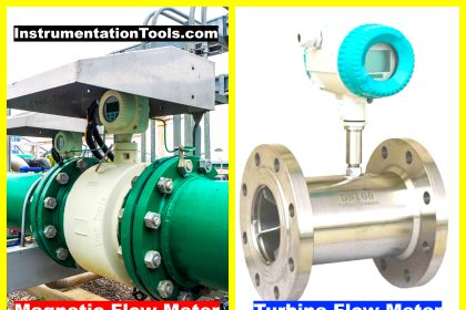
- Turbine Flow Meter Verification
- Practical Calibration Standard
- Digital Control Valve Principle
- Temperature Bath Calibration


Good to always check out the P&ID to get a feel of what the Instrument is doing there in the process;
1. Alarms and shutdown functions need to be taken care of reference to the C&E chart.
2. If it is in a control loop, the controller needs to be taken into manual control.
The above needs to be discussed with the operations and ONLY IF they agree do you need to prepare a PTW.
Or else all the time is wasted that day.
Usually, the above study is done the previous day when planning for the next day’s jobs.