The superheated steam is generated at the Boiler and is distributed to various locations in the plant through a steam piping network.
In the process industry, there are several auxiliaries at different locations that require different steam parameters (Steam pressure & temperature).
According to their application in the Process Industry requirement, the Superheated Steam Temperature and Pressure are reduced in PRDS.
PRDS is known as the Pressure Reducing and Desuperheating System.
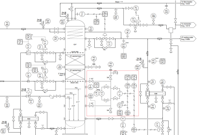
Pressure Reducing and Desuperheating Station
The PRDS usually has two types
- Split Type PRDS: In split type, two separate Steam Inlets are provided for the Pressure Reducing Stations and De-Super heater (DSH).
- Combined Type PRDS: In the Combined type, the Pressure Reducing Station and De-Super heater (DSH) are at the same Steam Inlet.
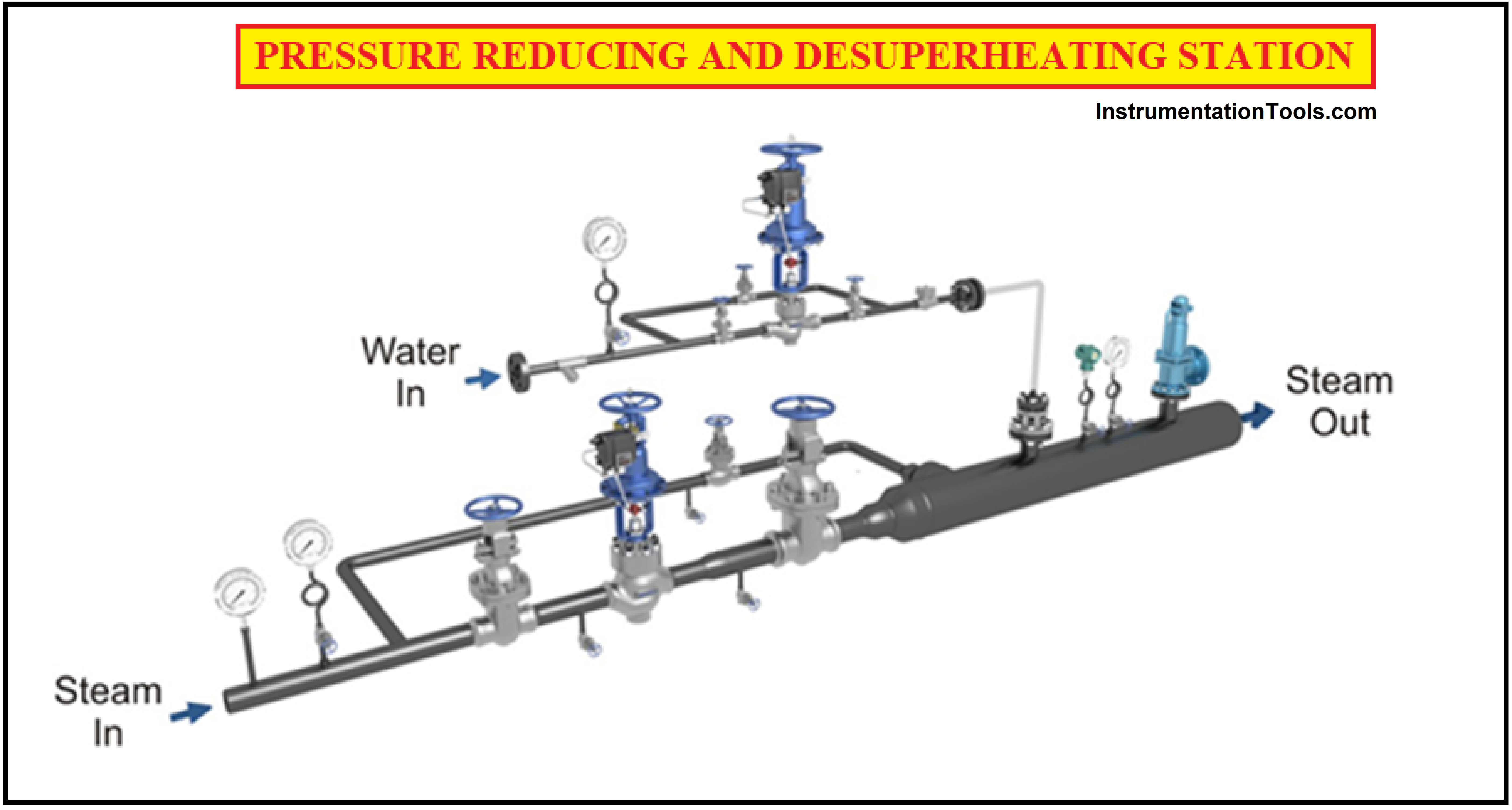
As the name implies, the Pressure Reducing and Desuperheating Station (PRDS) is a unit that conditions steam from a Main System (Boiler) to an Auxiliary Steam source of supply by reducing steam Pressure and Temperature using a Pressure Control Valve and a Temperature Control valve.
After Pressure Reduction is done, the steam is then allowed to pass through the Desuperheating station to lower the temperature of the steam to the required value.
Components of the PRDS
PRDS is a combination of Mechanical and Instrumentation components.
- Pressure Control Valve: It is known as a Pressure Reducing Valve or Pressure Control Valve. The Pressure Control Valve is the main component of the PRDS System. This is used to reduce the pressure of the superheated steam.
In General, the Control Valve is Known as the Final Control Element. And it is the heart of the Instrumentation Loop.
- Temperature Control valve: it is also known as a De-Super heater or Attemperator, This unit reduces the temperature of the super-heated steam that consists of Flow Nozzles, through which atomized water is sprayed to steam to reduce the temperature.
- Positioner: A Positioner in a Control Valve is a device that interfaces with the PID controller and senses the exact position of the control valve Stem. The Positioner sends the Instrument Air to the Actuator so that the position of the valve stem changes accordingly.
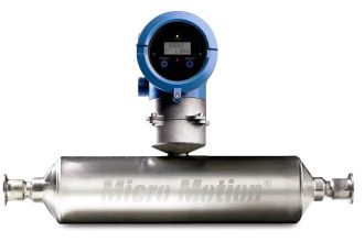
- Flow Meter: Flow Meter is a device that measures the exact value of the fluid flowing through it. Usually, the flow is measured in Tons Per Hour (TPH).
- Temperature Element: The Temperature Element senses or detects the hotness or coolness of the body.
- Pressure Gauge: It is a Pressure sensing device, it only displays the pressure of the fluid flowing through the line.
- Pressure Transmitters: This Pressure Transmitter Transmits the Pressure Value as the Process Variable (Measured value) to the controller.
- Temperature Gauge: It is a Temperature sensing device, it only displays the temperature of the fluid flowing through the line.
- Temperature Transmitter: This Temperature Transmitter (TT) receives the signal value from the Temperature Element (RTD/TC), and transmits the Measured Value as the Process Variable to the controller.
- Isolation valves: These valves are installed before and after the Control Valve to isolate the fluid flow when the control valve is in maintenance.
- Safety Valve: The Safety Valve in the System protects the whole system, when the pressure exceeds the preset limit, the valve opens the body and vents the excess pressure into the atmosphere.
A safety Valve is the most Essential Component in High-pressure Operation.
Operation of PRDS
In a Pressure Reducing and Desuperheating control system, there exist two loops,
- Pressure Loop Control System
- Temperature Loop Control System
Pressure Loop Control System
Components of Pressure Loop Control System:
This system includes a
- Pressure Control Valve (PCV),
- Pressure Transmitter (PT),
- PID Controller,
- I/P Converter,
- Pressure Gauges (PG), etc.
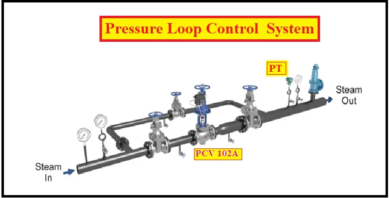
The Pressure Control Valve (PCV) in the Pressure loop control system reduces the pressure of the superheated steam by opening the Valve.
The Pressure Value to be reduced is given as a set point to the controller. The Pressure Transmitter senses the outlet Steam Pressure and sends the proportional signal to the PID controller as a Measured value.
The PID controller then compares the Process Variable (Measured Value) received from the Pressure Transmitter with the given SetPoint (SP) and generates an error signal which is then given to the Positioner of the Pressure Control Valve (PCV).
The Control Valve opens and relieves excess Pressure until the Pressure reaches the desired value. When the Steam Pressure reaches the Desired Set Point the control valve gets closed and prevents the further release of Pressure after normal conditions have been restored,
i.e. Process Variable (PV) must be equal to SetPoint (SP).
PV=SP
The Steam Inlet Isolation Valve and Outlet Isolation Valve of the Pressure Control Valve (PCV) are controlled with two remotely operated motorized valves for isolating the Pressure Control Valve during maintenance.
Temperature Loop Control System
Components of Temperature Loop Control system:
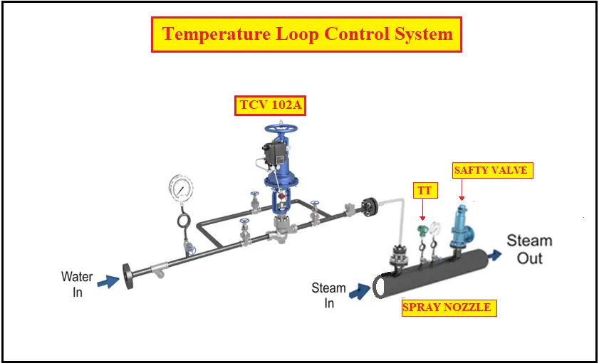
This System includes a
- Temperature control valve (TCV),
- Temperature Element (TE),
- Temperature Transmitter (TT),
- PID Controller,
- I/P Converter,
- Temperature Gauge (TG).
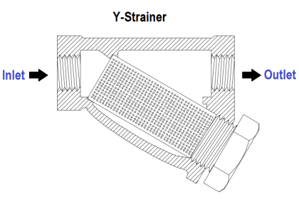
- The water strainer is provided at the inlet to prevent the entry of dust particles into the Temperature Control Valve & Spray nozzles.
- The Pressure Gauge at the inlet indicates the pressure of the atomized spray water.
- The Temperature Control Valve (TCV) regulates the quantity of the water to be sprayed.
- The water inlet and outlet isolation valves are used to isolate the Temperature Control Valve, whenever maintenance of the control valve is to be carried out.
- The Bypass valve allows spray water flow to continue whenever the Temperature Control Valve is under maintenance or becomes inoperable.
- The non-return valve prevents the backflow of steam into the water pipeline.
The Attemperation water is sprayed at high velocity through Spray nozzles in an adequate quantity. To reduce the temperature of superheated steam to the required temperature.
The Temperature element (TE) senses the outlet Steam Temperature and gives a proportional current signal to the PID controller via the Temperature transmitter (TT).
The PID controller then compares the Process Variable (Measured Value) received from the Temperature transmitter (TT) with a given SetPoint (SP), generates an error signal, and is then given to the Positioner of the Temperature Control Valve (TCV)
This valve opens accordingly and sprays atomized water through the spray nozzle until the steam temperature reaches the set value, and re-closes to prevent the further spray of water after normal conditions have been restored,
i.e. Process Variable (PV) must be equal to SetPoint (SP).
PV=SP
DeSuperheater has two types:
- Integral type DeSuperheater: In this type, the DeSuperheater is built with the actuator and a spray nozzle.
- Non-Integral type DeSuperheater: In this type DeSuperheater and spray nozzle are separate units.
Usually, all power plant uses Split type and Integrated-type PRDS
Applications of PRDS stations
- PRDS for process heating applications in sugar, food, textile, paper, etc.
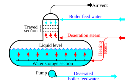
- Deaerator, Ejector PRDS for the boiler.
- Turbine By-pass PRDS.
The steam required for the process (Sugar Industries, Distilleries) is called exhaust steam which is at low temperature and pressure.
Note: Inlet Steam is the Main steam and outlet Steam is Exhaust Steam
A Safety Valve is used at the outlet of the system to ensure that the pressure does not exceed the preset limit. When the pressure exceeds the preset limit the safety valve opens and relieves the excess pressure to the atmosphere, when the pressure reaches its preset limit the Valve gets closed.


Fantastic article…Thanks for sharing such an amazing content with us.Good job.Keep it up.
Great article! Very clear and concise explanation of PRDS — easy to follow and well structured. 😊