Inst ToolsInst ToolsInst Tools
  • Courses
  • Automation
    • PLC
    • Control System
    • Safety System
    • Communication
    • Fire & Gas System
  • Instrumentation
    • Design
    • Pressure
    • Temperature
    • Flow
    • Level
    • Vibration
    • Analyzer
    • Control Valve
    • Switch
    • Calibration
    • Erection & Commissioning
  • Interview
    • Instrumentation
    • Electrical
    • Electronics
    • Practical
  • Q&A
    • Instrumentation
    • Control System
    • Electrical
    • Electronics
    • Analog Electronics
    • Digital Electronics
    • Power Electronics
    • Microprocessor
  • Request
Search
  • Books
  • Software
  • Projects
  • Process
  • Tools
  • Basics
  • Formula
  • Power Plant
  • Root Cause Analysis
  • Electrical Basics
  • Animation
  • Standards
  • 4-20 mA Course
  • Siemens PLC Course
Reading: How does SMPS Works? – Switched Mode Power Supply
Share
Notification Show More
Font ResizerAa
Inst ToolsInst Tools
Font ResizerAa
  • Courses
  • Design
  • PLC
  • Interview
  • Control System
Search
  • Courses
  • Automation
    • PLC
    • Control System
    • Safety System
    • Communication
    • Fire & Gas System
  • Instrumentation
    • Design
    • Pressure
    • Temperature
    • Flow
    • Level
    • Vibration
    • Analyzer
    • Control Valve
    • Switch
    • Calibration
    • Erection & Commissioning
  • Interview
    • Instrumentation
    • Electrical
    • Electronics
    • Practical
  • Q&A
    • Instrumentation
    • Control System
    • Electrical
    • Electronics
    • Analog Electronics
    • Digital Electronics
    • Power Electronics
    • Microprocessor
  • Request
Follow US
All rights reserved. Reproduction in whole or in part without written permission is prohibited.
Inst Tools > Blog > Animation > How does SMPS Works? – Switched Mode Power Supply

How does SMPS Works? – Switched Mode Power Supply

SMPS stands for Switched Mode Power Supply. In this article, you will learn how does SMPS works and their principle.

Last updated: May 23, 2023 2:30 pm
Viral Nagda
Animation Electrical Basics Electronic Basics PLC Tutorials
No Comments
Share
5 Min Read
SHARE

In this post, we will see the working of SMPS.

Contents
Switched Mode Power SupplyInput Rectifier and FilterHigh-Frequency ConverterPower TransformerOutput Rectifier and FilterControl Circuit

SMPS stands for Switched Mode Power Supply. It is an essential part of an electrical power circuit.

Basically, power is required in different forms for various circuits. So, we just cannot feed raw AC power to them. Such type of conversion is done by SMPS. Its role is to provide the necessary supply voltage to electrical circuits in their required form.

As the name implies, the power supply is altered and obtained in various forms by means of switching devices inside it. They switch the power in various ways to provide the final output voltage.

These switching devices are nothing but power electronic devices like triac, diac, transistor, MOSFET, capacitors, resistors, etc.

SMPS is majorly categorized into four types –

  1. AC to DC converter,
  2. DC to DC converter,
  3. Forward converter, and
  4. Flyback converter.

In this post, we will have a look at the working of one of the most widely used types – AC to DC converter.

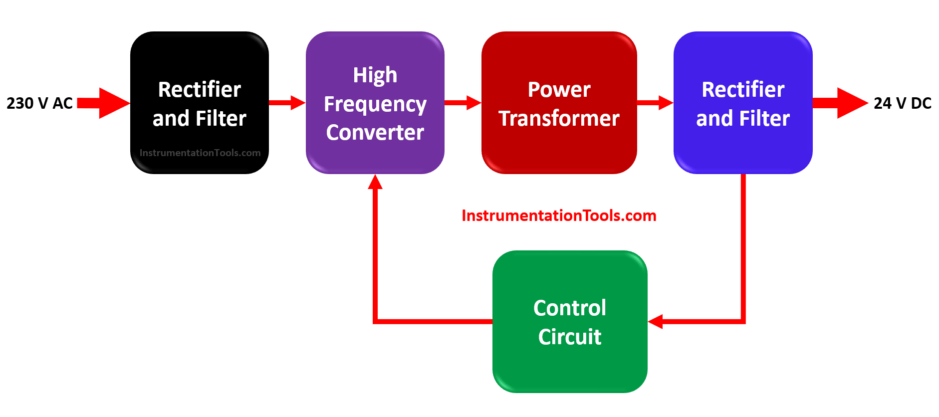
AC to DC converter is used to provide regulated DC supply voltage to electrical circuits. The 230V AC supply is converted to a 24V DC supply. Let us have a look at the inside circuit of this converter.

As seen in the below figure, the SMPS consists of an input rectifier and filter, a high-frequency switching device converter, power transformer, output rectifier, and filter and control circuitry.

Switched Mode Power Supply

Let us see the function of each of these components.

Switched Mode Power Supply (SMPS)

Input Rectifier and Filter

This is the primary stage of the converter. The rectifier and filter circuit is used to convert AC supply into DC voltage.

But this DC output voltage is unregulated. It has many variations as the circuit inside is only used to convert and not process it accurately.

This unregulated DC voltage is then given to a high-frequency converter consisting of switching devices.

High-Frequency Converter

This is the main heart of SMPS. Because the incoming DC voltage is unregulated and not processed properly, it cannot be directly fed to the output circuit.

So, the processing task is done by power-electronic switching devices. Power transistor, MOSFET, diac, triac, etc. are employed here which switches on and off according to variations.

These switching devices have very low resistance and they are capable of resisting high currents. They thus create high frequency pulsating DC signal; which is processed properly and less variable.

Power Transformer

The high-frequency DC output is fed to the power transformer for step-down reduction.

The high voltage DC output is converted into a low voltage DC output.

Switched Mode Power Supply Animation

Output Rectifier and Filter

The output from the transformer is again fed to the rectifier and filter circuit to get a constant and steady DC output voltage.

Basically, this filter smoothens the DC output.

Control Circuit

Similar to PID philosophy, the output from rectifier is again fed to the high-frequency device for feedback error control logic.

This is done to ensure that we get a constant DC output voltage every time. The deviations are monitored and nullified again by the whole circuit once again.

SMPS find their application in almost every electrical circuit, as most of the devices require DC voltage; and not just DC voltage, SMPS provides a regulated voltage as discussed before in the types of SMPS.

If you liked this article, then please subscribe to our YouTube Channel for Electrical, Electronics, Instrumentation, PLC, and SCADA video tutorials.

You can also follow us on Facebook and Twitter to receive daily updates.

Read Next:

  • What is a Wet Contact?
  • Preventive Maintenance of VFD
  • Why 24 Volts DC Power Supply?
  • Commissioning and Testing of PLC
  • Automation Engineer Troubleshooting
Don't Miss Our Updates
Be the first to get exclusive content straight to your email.
We promise not to spam you. You can unsubscribe at any time.
Invalid email address
You've successfully subscribed !

Continue Reading

Electric Motor Forward Reverse with Repeat Cycle PLC Logic
PLC Program – Controls Conveyors ON and OFF Sequence
Ferrules and Cross Ferruling
PID Controllers in Closed Loop Control Systems – PLC Basics
Workstation Healthiness Checks
Example of Flip-Flop PLC Program for Lamps Application
Share This Article
Facebook Whatsapp Whatsapp LinkedIn Copy Link
Share
Leave a Comment

Leave a Reply Cancel reply

Your email address will not be published. Required fields are marked *

Stay Connected

128.3kFollowersLike
69.1kFollowersFollow
210kSubscribersSubscribe
38kFollowersFollow

Categories

Explore More

Difference Between PLC and CNC Machine
Standard Colors in PLC Automation Systems
Motor Stop Interlock for Changing the Direction PLC Program
Automatic Curtain Control – PLC Programming Solution
How to Configure PID in Siemens PLC?
Redundant Automation Systems – Need and Advantages
Comparison Instructions in PLC Programming
Basics of Voltage Regulator

Keep Learning

PLC Programming for Train Detection and Gate Operation

PLC Programming for Train Detection and Gate Operation

Can a PLC Function Without an HMI or SCADA

Can a PLC Function Without an HMI or SCADA?

Multi Way Switches using PLC

Making Multi Way Switches using PLC

Allen Bradley SLC 500 PLC Programming

How to Download Rslogix Free

Download Allen Bradley RSLogix PLC Software

Search tank in Intouch Scada

Tank Filling and Emptying using Intouch Scada Script

Use PLC Flags as Integrity Checks

#4 PLC Best Practices – Use PLC Flags as Integrity Checks

Controlling of Tank Level Using Proportional Controller in PLC

Controlling of Tank Level Using Proportional Controller in PLC

Learn More

noise-abatement trim

Control Valve Noise Problems

Procedure For reading or searching the tag number in Siemens PLC

Procedure for Reading or Searching the Tag number in Siemens PLC

Identify Valve Parts Quiz with Answers

Identify Valve Parts Quiz with Answers

Two Hand Press PLC

Two Hand Press Safety Control Circuit

Pressure Gauge with Block and Bleed Valves

Pressure Gauge with Block and Bleed Valves

Ratio Control Example

Ratio Controller Example

Measurement and Instrumentation Objective Questions

Measurements & Instrumentation Quiz – Set 2

Hand Switch Pressed Working Animation

Pushbutton switches and Types of Switches

Menu

  • About
  • Privacy Policy
  • Copyright

Quick Links

  • Learn PLC
  • Helping Hand
  • Part Time Job

YouTube Subscribe

Follow US
All rights reserved. Reproduction in whole or in part without written permission is prohibited.
Welcome Back!

Sign in to your account

Username or Email Address
Password

Lost your password?