Inst ToolsInst ToolsInst Tools
  • Courses
  • Automation
    • PLC
    • Control System
    • Safety System
    • Communication
    • Fire & Gas System
  • Instrumentation
    • Design
    • Pressure
    • Temperature
    • Flow
    • Level
    • Vibration
    • Analyzer
    • Control Valve
    • Switch
    • Calibration
    • Erection & Commissioning
  • Interview
    • Instrumentation
    • Electrical
    • Electronics
    • Practical
  • Q&A
    • Instrumentation
    • Control System
    • Electrical
    • Electronics
    • Analog Electronics
    • Digital Electronics
    • Power Electronics
    • Microprocessor
Search
  • Books
  • Software
  • Projects
  • Process
  • Tools
  • Basics
  • Formula
  • Power Plant
  • Root Cause Analysis
  • Electrical Basics
  • Animation
  • Standards
  • 4-20 mA Course
  • Siemens PLC Course
Reading: Magnehelic Gauge Calibration
Share
Notification Show More
Font ResizerAa
Inst ToolsInst Tools
Font ResizerAa
  • Courses
  • Design
  • PLC
  • Interview
  • Control System
Search
  • Courses
  • Automation
    • PLC
    • Control System
    • Safety System
    • Communication
    • Fire & Gas System
  • Instrumentation
    • Design
    • Pressure
    • Temperature
    • Flow
    • Level
    • Vibration
    • Analyzer
    • Control Valve
    • Switch
    • Calibration
    • Erection & Commissioning
  • Interview
    • Instrumentation
    • Electrical
    • Electronics
    • Practical
  • Q&A
    • Instrumentation
    • Control System
    • Electrical
    • Electronics
    • Analog Electronics
    • Digital Electronics
    • Power Electronics
    • Microprocessor
Follow US
All rights reserved. Reproduction in whole or in part without written permission is prohibited.
Inst Tools > Blog > Calibration > Magnehelic Gauge Calibration

Magnehelic Gauge Calibration

This article cover calibration of Magnehelic Gauge (Differential Pressure Gauge) using Digital Manometer.

Last updated: September 28, 2022 3:24 pm
Saurabh Vaidya
Calibration Pressure Measurement
No Comments
Share
4 Min Read
SHARE

This article cover calibration of Magnehelic Gauge (Differential Pressure Gauge) using a Digital Manometer.

Contents
Magnehelic Gauge CalibrationUp-Cycle CalibrationDown-Cycle Calibration

Magnehelic Gauge or Differential Pressure Gauge has two ports – High and Low.

As name suggest Differential Pressure Gauge i.e. its measure Pressure difference between High port and Low port.

Generally, units of Differential pressure Gauge are mmWC, Pascal, Mbar, Inch WC, PSI, mmHg

High Port is also called as Positive port and Low port is called as Negative port.

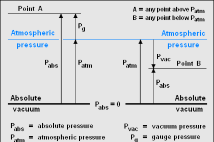
How to calculate differential pressure?

Pressure at high port is 100 Pascal and Pressure at low port is 75 Pascal.

Differential Pressure indicated by Magnehelic Gauge or Differential Pressure Gauge is 100-75= 25 Pascal,

Differential Pressure= High Port – Low Port

If pressure at Low Port is higher than Low Port, than indicator will show Negative readings.

Magnehelic Gauge Calibration

Magnehelic Gauge Calibration

Analog Magnehelic Gauge should be in Vertical position.

Generally, Magnehelic Gauge is installed above the door, input ports with a hose are located at the back and front of the gauge. So opening the door will equalize the ambient pressure and the Magnehelic gauge will turn back to zero (as both rooms are at equal pressure, High port – Low Port = 0)

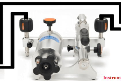
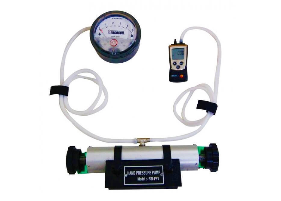
Connect the pneumatic pump on the High Port of the Magnehelic Gauge. Leave the Low Port open to ambient, in this way, the differential pressure gauge functions as a normal pressure gauge. 

 You can also connect Low Port to know Pressure and find the difference between High and low port.

The calibration Procedure from this step is the same as the Pressure Gauge.  I.e. Preloading, UP Cycle, Down Cycle.

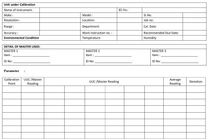
Equally distribute calibration points into 5 points (0%, 25%, 50 %, 75% and 100%)

Pre Loading – Increase Pressure up to full scale & decrease it to zero of UUC, to make pointer movement free.

We should wait at least 30 seconds to note the readings of Magnehelic Gauge. The waiting time for the upper limit of the measuring range is 2 minutes.

Up-Cycle is measured from Minimum pressure range to Maximum Pressure Range

Down-Cycle is measured from Maximum pressure range to Minimum Pressure Range

Up-Cycle Calibration

  • Increase Pressure by operating the pump to set the calibration point on the UUC gauge.
  • When pointer of UUC Gauge reach first calibration point note down both UUC & standard reading. Wait for 30 seconds to note down reading. Wait for 2 Minutes for upper limit of measuring range.
  • Slowly increase the pressure to set next set point .Write down reading Standard reading & UUC reading.
  • Repeat this procedure for remaining calibration points.
  • This completes Up cycle of calibration of Magnehelic Gauge

Down-Cycle Calibration

  • For Down Cycle, Last calibration point of Up Cycle is first point of Down Cycle.
  • Slowly decrease the pressure to set the next set point. Write down reading Standard reading & UUC reading. Wait for 30 seconds to note down reading. Wait for 2 Minutes for the upper limit of the measuring range.
  • Repeat this procedure for remaining calibration points.
  • This completes the Down Cycle of calibration of Magnehelic Gauge

If you liked this article, then please subscribe to our YouTube Channel for Instrumentation, Electrical, PLC, and SCADA video tutorials.

You can also follow us on Facebook and Twitter to receive daily updates.

Read Next:

  • History of Measurement
  • Pressure Gauge Calibration
  • Selection of Master Instrument
  • Importance of Unit Measurement
  • Reliability Centered Maintenance
Don't Miss Our Updates
Be the first to get exclusive content straight to your email.
We promise not to spam you. You can unsubscribe at any time.
Invalid email address
You've successfully subscribed !

Continue Reading

Calibration of Measuring Instruments – Significance, Costs & Risks
Motor Operated Valve Functional Testing
Hierarchy of Calibration Organizations
Conductivity Transmitter Calibration Procedure
Electrical Standards
Closed Tank Remote Seal Capillary type DP Transmitter
Share This Article
Facebook Whatsapp Whatsapp LinkedIn Copy Link
Share
Leave a Comment

Leave a Reply Cancel reply

Your email address will not be published. Required fields are marked *

Stay Connected

128.3kFollowersLike
69.1kFollowersFollow
210kSubscribersSubscribe
38kFollowersFollow

Categories

Explore More

Selection of Weighing Balance and Weight for Calibration
Top 30 Interview Questions on Pressure Measuring Devices
Closed tank DP Level Transmitter with wet leg elevation zero direct mount Calibration
Bourdon Tube Pressure Gauge Working Principle Animation
Displacer Level Transmitter Dry Calibration with Weights
Importance of Unit Measurement
Questions on Pressure Transmitter Calibration Setup
Foundation Fieldbus Transmitter Calibration

Keep Learning

Differential Pressure Sensor for Filtration Monitoring

Differential Pressure Sensor for Filtration Monitoring

Diaphragm

Diaphragms

Differential Pressure Transmitter Question

Differential Pressure Transmitter Questions

Fine wire strain gauge

Fine Wire Strain Gauge Principle

Pressure gauges with capsule elements

Pressure Gauges with Capsule Sensor Principle

Hammer Effect in Gauges

What is Hammer Effect in Gauges ?

Technologies for Oxygen Gas Measurement

How to Calibrate Oxygen Analyzer? – O2 Sensor Testing Procedure

Pig Signalling Switches Functional Testing

Pig Signalling Switches Functional Testing

Learn More

Dissolved oxygen measurement using Optical Fiber Communication

Fiber Optic Sensors

Pressure Gauge Water traps and pigtail siphons

Pressure Gauge Water Traps and Pigtail Siphons

Control Sytem Open Loop and Closed Loop

Introduction to Control System

How PLC controls a ON-OFF Valve

PLC Valve Control Ladder Logic Programming

interview-questions-and-answers-on-natural-gas

Oil and Gas Interview Questions Answers

How to Run Multiple Motors with a Single VFD

How to Run Multiple Motors with a Single VFD?

DC Machine

DC Machines Construction

Humidity Sensing Absorption Hydrometer Principle

Humidity Sensing Absorption Hydrometer Principle

Menu

  • About
  • Privacy Policy
  • Copyright

Quick Links

  • Learn PLC
  • Helping Hand
  • Part Time Job

YouTube Subscribe

Follow US
All rights reserved. Reproduction in whole or in part without written permission is prohibited.
Welcome Back!

Sign in to your account

Username or Email Address
Password

Lost your password?