Inst ToolsInst ToolsInst Tools
  • Ask
  • Courses
  • Videos
  • Q & A
    • Interview
      • Instrumentation
      • Electronics
      • Electrical
      • Practical Questions
    • MCQ
      • Instrumentation MCQ
      • Electrical MCQ
      • Electronics MCQ
      • Control Systems MCQ
      • Analog Electronics MCQ
      • Digital Electronics MCQ
      • Power Electronics MCQ
      • Microprocessor MCQ
      • Multiple Choice Questions
  • EE
    • Electronics
      • Electronics Q & A
      • Electronic Basics
      • Electronic Devices & Circuits
      • Electronics Animation
      • Digital Electronics
    • Electrical
      • Electrical Basics
      • Electrical Q & A
      • Power Electronics
      • Electrical Machines
      • Electrical Animation
      • Power Systems
      • Switchgear & Protection
      • Transmission & Distribution
  • Measure
    • Control Valves
    • Calibration
    • Temperature
    • Pressure
    • Flow
    • Level
    • Analyzers
    • Switches
    • Vibration
    • Solenoid Valve
  • Control
    • PLC Tutorials
    • Control Systems
    • Safety Instrumented System (SIS)
    • Communication
    • Fire & Gas System
  • More
    • Design
    • Tools
    • Animation
    • Basics
    • Formulas
    • Standards
    • TextBooks
    • Common
    • Software
    • Excel Tools
    • Erection & Commissioning
    • Process Fundamentals
    • Videos
    • Books
Search
All rights reserved. Reproduction in whole or in part without written permission is prohibited.
Reading: Signal Strength of Guided-wave Radar Level Instrument
Share
Notification Show More
Font ResizerAa
Inst ToolsInst Tools
Font ResizerAa
  • Courses
  • PLC Tutorials
  • Control Systems
Search
  • Ask
  • Courses
  • Videos
  • Q & A
    • Interview
    • MCQ
  • EE
    • Electronics
    • Electrical
  • Measure
    • Control Valves
    • Calibration
    • Temperature
    • Pressure
    • Flow
    • Level
    • Analyzers
    • Switches
    • Vibration
    • Solenoid Valve
  • Control
    • PLC Tutorials
    • Control Systems
    • Safety Instrumented System (SIS)
    • Communication
    • Fire & Gas System
  • More
    • Design
    • Tools
    • Animation
    • Basics
    • Formulas
    • Standards
    • TextBooks
    • Common
    • Software
    • Excel Tools
    • Erection & Commissioning
    • Process Fundamentals
    • Videos
    • Books
Follow US
All rights reserved. Reproduction in whole or in part without written permission is prohibited.
Inst Tools > Blog > Practical Questions > Signal Strength of Guided-wave Radar Level Instrument

Signal Strength of Guided-wave Radar Level Instrument

The following graph shows the signal strength received by a guided-wave radar (GWR) level instrument over time.

Last updated: December 24, 2020 7:03 pm
Editorial Staff
Practical Questions
No Comments
Share
1 Min Read
SHARE

The following graph shows the signal strength received by a guided-wave radar (GWR) level instrument over time:

Guided-wave Radar

Signal Strength of Guided-wave Radar Level Instrument

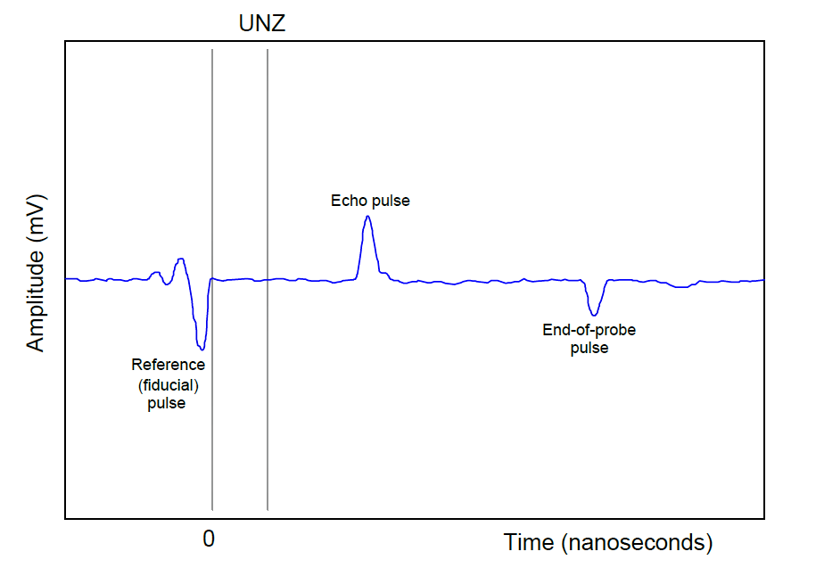
Explain how the graph will change if:

1. The liquid level increases

2. The dielectric constant (ε) of the liquid decreases

3. The density of the liquid decreases (assuming constant ε)

4. A liquid-liquid interface consisting of two liquids with different densities is introduced into the vessel

5. Also, explain what UNZ refers to (the Upper Null Zone).

6. Describe a practical reason for configuring a radar transmitter to have an upper null zone, and how this differs from a radar instrument’s transition zones.

7. Explain why the timing of both the echo pulse and the end-of-probe pulse will shift as liquid level changes in this system.

Share your answers and explanation with us through the below comments section.

Read Next:

  • Guided Wave Radar Questions
  • Ultrasonic Transmitter
  • Block and Bleed Valves
  • Stroke Checking Procedure
  • DP Transmitter Located

Credits: Tony R. Kuphaldt

Don't Miss Our Updates
Be the first to get exclusive content straight to your email.
We promise not to spam you. You can unsubscribe at any time.
Invalid email address
You've successfully subscribed !
DP Transmitter Block and Bleed Valves
Moving Pressure Sensing Level Transmitter from Top to Bottom
Define Normal Status of a Process Switch ?
Upgrading the Electrical System in an Automobile
A Question on Density Gauge
Share This Article
Facebook Whatsapp Whatsapp LinkedIn Copy Link
Share
Leave a Comment

Leave a Reply Cancel reply

Your email address will not be published. Required fields are marked *

Stay Connected

128.3kFollowersLike
69.1kFollowersFollow
208kSubscribersSubscribe
38kFollowersFollow

Categories

Recent Comments

  • Kamli on Top Free PLC Software
  • Guifty Shimica on Top Non-PLC Certification Courses for Automation Professionals
  • Guifty Shimica on Top Non-PLC Certification Courses for Automation Professionals
  • MIHARITSOA Aina Sitraka on Top Non-PLC Certification Courses for Automation Professionals

Related Articles

Calculate Amount of Weight Indicated by the Scale

Calculate Amount of Weight Indicated by the Scale

Level Loop Troubleshooting

Identify Faults in PID Control Loop

Current-to-Pressure Transducer Calibration Table

Which instrument is faulty

Which Instrument is Faulty? Transmitter, Recorder, or Controller

PLC program to control pump

Troubleshooting PLC Permissive Inputs

water seal drum lever transmitter

Determine LRV and URV settings for the Level Transmitter

A Question on Steam Drum Water Level Measurement

A Question on Steam Drum Water Level Measurement

PLC Program three-phase electric motor

Identify the Problem in the PLC Program

More Articles

PLC Control for Baking Machines Logic

PLC Programming for Baking with Auto and Manual Modes

PLC Programming Sequence Logic

PLC Programming to Control Lights in a Sequence

Determine the Problems with the Level Transmitter and Gauge

Determine the Problems with Level Transmitter and Gauge

YouTube Channels About Tech and Engineering

Awesome YouTube Channels About Tech and Engineering

Transistor Output Wiring

PLC Output Types

What is insulation

What is insulation? How to Choose the Insulation Material?

Mitsubishi PLC Programming Tutorials

Calculate the 0%, 50%, and 100% Calibration Points

Calculate the 0%, 50%, and 100% Calibration Points

Follow US
All rights reserved. Reproduction in whole or in part without written permission is prohibited.
Welcome Back!

Sign in to your account

Username or Email Address
Password

Lost your password?