Inst ToolsInst ToolsInst Tools
  • Courses
  • Automation
    • PLC
    • Control System
    • Safety System
    • Communication
    • Fire & Gas System
  • Instrumentation
    • Design
    • Pressure
    • Temperature
    • Flow
    • Level
    • Vibration
    • Analyzer
    • Control Valve
    • Switch
    • Calibration
    • Erection & Commissioning
  • Interview
    • Instrumentation
    • Electrical
    • Electronics
    • Practical
  • Q&A
    • Instrumentation
    • Control System
    • Electrical
    • Electronics
    • Analog Electronics
    • Digital Electronics
    • Power Electronics
    • Microprocessor
  • Request
Search
  • Books
  • Software
  • Projects
  • Process
  • Tools
  • Basics
  • Formula
  • Power Plant
  • Root Cause Analysis
  • Electrical Basics
  • Animation
  • Standards
  • 4-20 mA Course
  • Siemens PLC Course
Reading: Turbine Bypass System
Share
Notification Show More
Font ResizerAa
Inst ToolsInst Tools
Font ResizerAa
  • Courses
  • Design
  • PLC
  • Interview
  • Control System
Search
  • Courses
  • Automation
    • PLC
    • Control System
    • Safety System
    • Communication
    • Fire & Gas System
  • Instrumentation
    • Design
    • Pressure
    • Temperature
    • Flow
    • Level
    • Vibration
    • Analyzer
    • Control Valve
    • Switch
    • Calibration
    • Erection & Commissioning
  • Interview
    • Instrumentation
    • Electrical
    • Electronics
    • Practical
  • Q&A
    • Instrumentation
    • Control System
    • Electrical
    • Electronics
    • Analog Electronics
    • Digital Electronics
    • Power Electronics
    • Microprocessor
  • Request
Follow US
All rights reserved. Reproduction in whole or in part without written permission is prohibited.
Inst Tools > Blog > Control Systems > Turbine Bypass System

Turbine Bypass System

Turbine bypass system protects the turbine, boiler, and condenser from damage by providing an alternate flow path for the steam,

Last updated: December 13, 2020 7:51 pm
Editorial Staff
Control Systems Power Plant
No Comments
Share
6 Min Read
SHARE

The turbine bypass system has evolved over the last few decades as the mode of power plant operations has changed. It is employed routinely in utility power plants where operations require quick response to wide swings in energy demands.

Contents
Turbine Bypass System ComponentsTurbine Bypass ValvesTurbine Bypass Water Control ValvesElectro-Hydraulic SystemMajor Functions of Turbine Bypass System

A typical day of power plant operation might start at minimum load, increase to full capacity for most of the day, rapidly reduce back to minimum output, and then up again to full load—all within a twenty-four hour period. Boilers, turbines, condensers and other associated equipment cannot respond properly to such rapid changes without some form of turbine bypass system.

The turbine bypass system allows operation of the boiler independent of the turbine. In the start-up mode, or rapid reduction of generation requirement, the turbine bypass not only supplies an alternate flow path for steam, but conditions the steam to the same pressure and temperature normally produced by the turbine expansion process.

By providing an alternate flow path for the steam, the turbine bypass system protects the turbine, boiler, and condenser from damage that may occur from thermal and pressure excursions. For this reason, many turbine bypass systems require extremely rapid open/close response times for maximum equipment protection. This is accomplished with an electro hydraulic actuation system that provides both the forces and controls for such operation.

Additionally, when commissioning a new plant, the turbine bypass system allows start-up and check out of the boiler separately from the turbine. This means quicker plant start-ups, which results in attractive economic gains. It also means that this closed loop system can prevent atmospheric loss of treated feed water and reduction of ambient noise emissions.

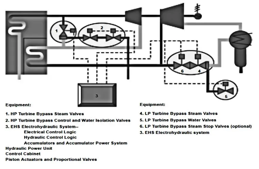
Turbine Bypass System Components

Turbine Bypass System

Image Courtesy: Fisher

The major elements of a turbine bypass system are turbine bypass valves, turbine bypass water control valves, and the electro-hydraulic system.

Turbine Bypass Valves

Whether for low-pressure or high pressure applications, turbine bypass valves are usually the manifold design steam conditioning valves previously described with tight shutoff (Class V).

Because of particular installation requirements these manifold design valves will occasionally be separated into two parts: the pressure-reducing portion of the valve and then the outlet/ manifold cooler section located closer to the condenser.

Regardless of the configuration, however, a cost effective solution is a fixed-orifice device (usually a sparger) located downstream for final pressure reduction to minimize the size of the outlet pipe to the condenser.

Turbine Bypass Water Control Valves

These valves are required to control the flow of the water to the turbine bypass valves. Due to equipment protection requirements, it is imperative that these valves provide tight shutoff (Class V).

Electro-Hydraulic System

This system is for actuating the valves. Its primary elements include the actual hydraulic actuators, the hydraulic accumulator and power unit, and the control unit and operating logic.

Major Functions of Turbine Bypass System

The steam turbine bypass system will allow the operator to keep the gas turbine and the heat recovery system generator (HRSG) on-line in the event of a steam turbine trip or to facilitate faster start-ups of the CT and HRSG. The turbine bypass system also enables a combined cycle plant to operate at turndown conditions.

During start-up and/or turbine trips, the steam dump control valves control the pressure and flow through the main and IP steam lines. Meanwhile, the attemperation system controls the temperature into the reheat inlet and condenser. These two components working together maintain the pressures and temperatures of the steam system, insure stable drum level control during a trip event, and allows for a faster re-start of the steam turbine.

The turbine bypass system’s major function is to isolate the bypass loop during normal operation. The valves contained within the system MUST have tight isolation, as the system is isolated 95% of the time or more. Failure to properly isolate the system results in damaged seats and valves, which result in lost energy and loss of control during start-up and turbine trips.

Another major function of the turbine bypass system is to avoid a steam system overpressure event, resulting in the lifting of safety valves, and subsequently creating a maintenance/outage problem associated with repairing the valves.

To accomplish this, the bypass valves operating in “fast-acting“ (vs. modulating) mode actuates upon sensing an overpressure event in the main steam and/or hot reheat lines, or upon receipt of a steam turbine generator trip signal.

The turbine bypass system diverts the system flow around the steam turbine generator to the condenser, which provides the ultimate heat sink. This serves to drop the system pressure, while still passing sufficient flow to maintain HRSG superheater and reheater section cooling. The valves on this part of the system act as “steam dump valves”
Don't Miss Our Updates
Be the first to get exclusive content straight to your email.
We promise not to spam you. You can unsubscribe at any time.
Invalid email address
You've successfully subscribed !

Continue Reading

Motor Control Signal Interface
Difference Between SCADA and HMI
Turbine Speed Control system using Woodward Governor
How Valve Positioners act as Cascade Control Systems in a Loop?
What is Override Control? – Need & Applications
Burner Safety Logic for Initial Lighting
Share This Article
Facebook Whatsapp Whatsapp LinkedIn Copy Link
Share
Leave a Comment

Leave a Reply Cancel reply

Your email address will not be published. Required fields are marked *

Stay Connected

128.3kFollowersLike
69.1kFollowersFollow
210kSubscribersSubscribe
38kFollowersFollow

Categories

Explore More

Motor Control Center (MCC) Signal Interface Termination (SIT)
DCS versus PLC Architecture
What is Data Acquisition? – Elements and Components
How to Write a Program in Ecostruxure Machine Expert HVAC Software?
What is a Active Barrier ?
Types of Wireless Technologies in Industrial Automation
Design Process Graphics in Factory Talk View Studio with an Analog Input
Siemens PLC Course for Beginners: Problems and Solutions

Keep Learning

Turbine Meter in Gas Metering System

Read Gas Composition from Gas Metering System using RS485 Protocol

What is Gear Run Out

What is Gear Run Out ?

Boiler Feed Water Treatment

Boiler Feed Water Treatment

Boiler Protection System

Burner Management System Logic and Interlock

PID Tuner

Free PID Controller Gains Tuning Tool

Level Control Loop Principle

Integrating Processes – Liquid Level Control

Heuristic PID Tuning Procedure

Heuristic PID Tuning Procedure

How Engineers Effectively do Problem-solve and Troubleshoot

How Engineers Effectively do Problem-solve and Troubleshoot?

Learn More

Basics of PID Controllers

PID Controllers in Closed Loop Control Systems – PLC Basics

Power Electronics Objective Questions

1 Phase Voltage Source Inverter Quiz

Chlorine dioxide measurement principle

Chlorine dioxide Analyzer Principle

Fire Hydrant System

Basics of Fire Fighting Hydrant Systems

Clamp Meter

What is a Clamp Meter?

Oval gear Flow Meter Principle

Oval Gear Meter – Principle, Advantages, Limitations, Applications

Leaking Plug Valves pose Safety Hazards and Lead to Plant Shutdown

Leaking Plug Valves Pose Safety Hazards and Lead to Plant Shutdown

Float-type Level Switch for Sensing Low Oil Level

Float-type Level Switch for Sensing Low Oil Level

Menu

  • About
  • Privacy Policy
  • Copyright

Quick Links

  • Learn PLC
  • Helping Hand
  • Part Time Job

YouTube Subscribe

Follow US
All rights reserved. Reproduction in whole or in part without written permission is prohibited.
Welcome Back!

Sign in to your account

Username or Email Address
Password

Lost your password?