By using this site, you agree to the Privacy Policy and Terms of Use.
Accept
Inst ToolsInst ToolsInst Tools
  • Courses
  • PLC Tutorials
  • Control Systems
Search
All rights reserved. Reproduction in whole or in part without written permission is prohibited.
Reading: What is Cable Schedule and Junction Box Schedule?
Share
Notification Show More
Font ResizerAa
Inst ToolsInst Tools
Font ResizerAa
  • Courses
  • PLC Tutorials
  • Control Systems
Search
  • Ask
  • Courses
  • Videos
  • Q & A
    • Interview
    • MCQ
  • EE
    • Electronics
    • Electrical
  • Measure
    • Control Valves
    • Calibration
    • Temperature
    • Pressure
    • Flow
    • Level
    • Analyzers
    • Switches
    • Vibration
    • Solenoid Valve
  • Control
    • PLC Tutorials
    • Control Systems
    • Safety Instrumented System (SIS)
    • Communication
    • Fire & Gas System
  • More
    • Design
    • Tools
    • Animation
    • Basics
    • Formulas
    • Standards
    • TextBooks
    • Common
    • Software
    • Excel Tools
    • Erection & Commissioning
    • Process Fundamentals
    • Videos
    • Books
Follow US
All rights reserved. Reproduction in whole or in part without written permission is prohibited.
Inst Tools > Blog > Instrumentation Design > What is Cable Schedule and Junction Box Schedule?

What is Cable Schedule and Junction Box Schedule?

Last updated: August 14, 2020 9:23 am
Editorial Staff
Instrumentation Design
No Comments
Share
4 Min Read
SHARE

Cable and Junction Box schedules are deliverables prepared by instrumentation and control design engineers in EPC or EPCM Companies. In this article, we shall learn about the same.

Contents
Inputs RequiredCable ScheduleJunction Box ScheduleThe typical Junction Box layoutRead Next:

Inputs Required

 Below listed references are the required inputs for the preparation of the document “Cable Schedule”.

  • P&IDs
  • Instrument Index and Instrument I/O List
  • I&C Design Basis
  • Basic Engineering Design Data

Cable Schedule

Cable Schedule is a document containing a list of Instrument cables. This document shows cable as well as gland required by each instrument or connection.

The information of the cable schedule consists:

  • Cable Number
  • Cable Type / Specification
  • Cable Size
  • Cable Length
  • Source and destination termination description
  • Cable gland type and size for each incoming cable

Cable schedule is a reference in preparing Material Take-Off of cable for procurement. However, cable length shown on this document is approximate only. Therefore, there should be a contingency for material procurement to allow spare for cable cutting, unexpected barriers in the field, riser, etc.

Cable schedule will be referred also during the construction phase; however, it is not recommended to cut the cable based on the length information stated on the cable schedule. For actual cutting during installation, the common practice is to pull the cable from its drum and cut it in the field.

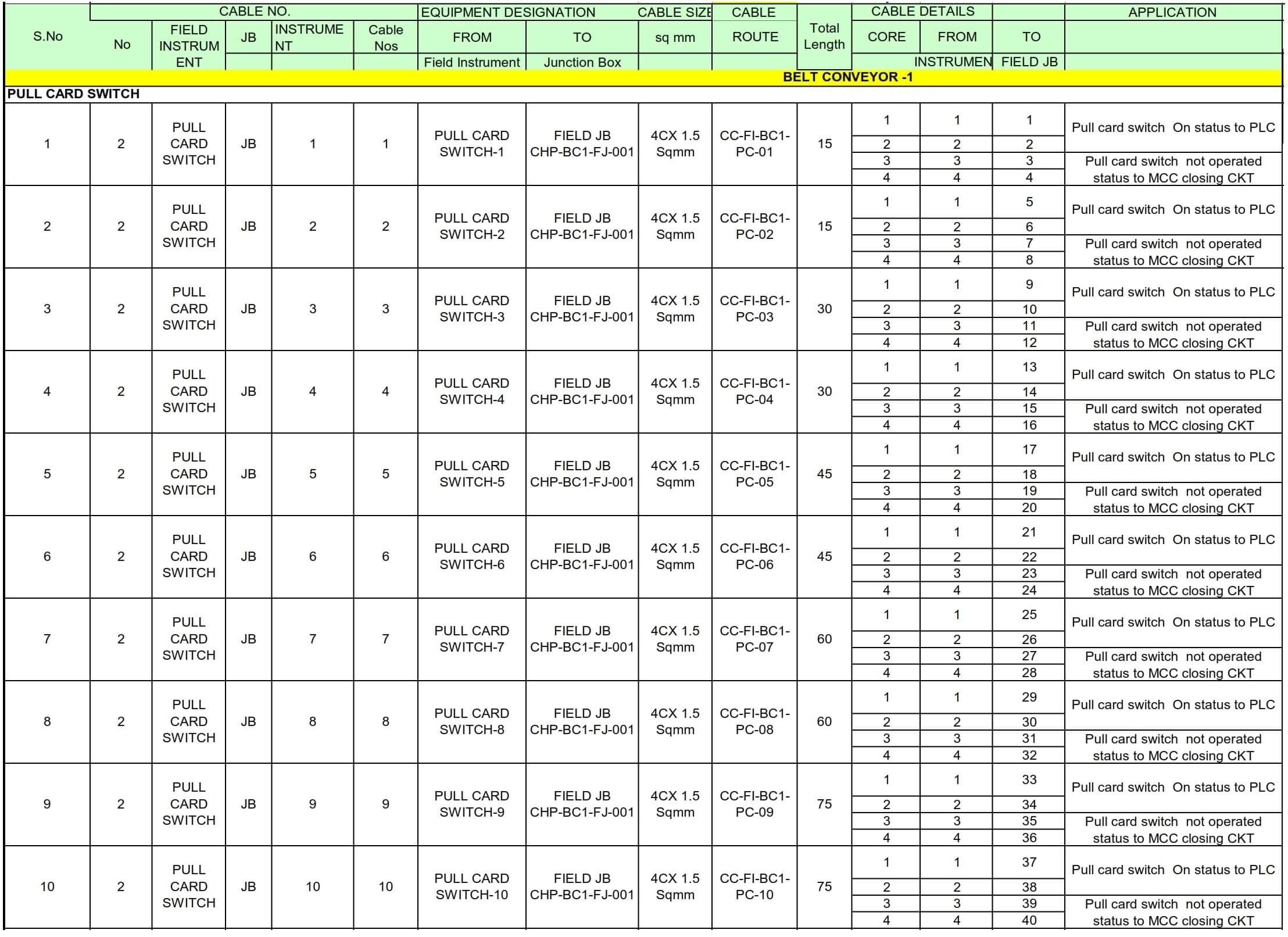
This is how a typical Cable schedule looks like.

Cable Schedule

Junction Box Schedule

First, let us learn about the Junction Box.

The junction box is an enclosure used for cables interconnection between field devices and the control room.

It encloses terminal strips for cable termination. Junction box shall be designed to suit environmental condition where the box will be installed and shall have certification of Ingress Protection code and hazardous area protection which conform to the classified area.

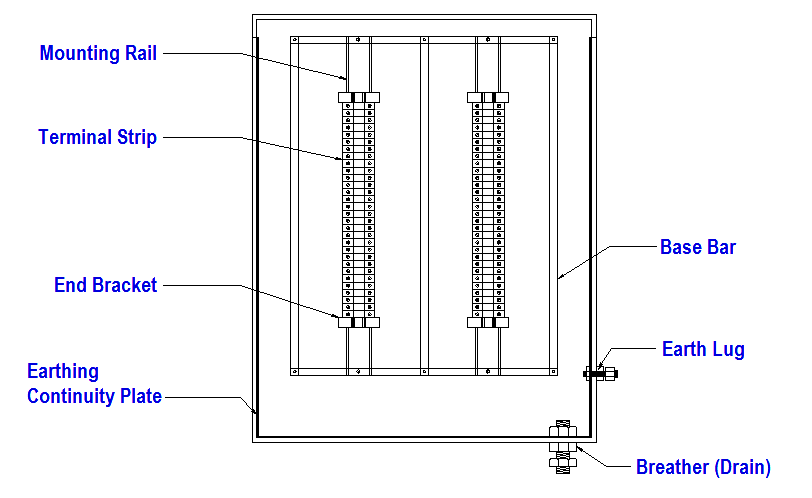
Junction Box consists of the following parts, but not limited to:

  • The terminal block which comprises terminal strips for cable connections
  • Gland plate (for non-metallic junction box) for cable gland earthing
  • An insulated earth bus bar for overall cable screen termination (optional, drain wire could be connected to terminal strip)
  • Breather/drain plug
  • Mounting Rail complete with end bracket

The typical Junction Box layout

Junction Box layout

JB Schedule is a document containing a list of instrument JB. This document shows cable as well as gland required by each instrument or connection.

The information of the JB schedule consists:

  • JB Number
  • JB Type / Specification
  • JB Size
  • JB Location/Area
  • Source and destination termination description
  • gland type and size for each incoming cable

JB schedule is a reference in preparing Material Take-Off of JBs for procurement.

JB schedule will be referred also during the construction phase, however, it is not recommended to install JBs based on the location information stated on the JB schedule. For actual installation, the common practice is to refer Location Layout.

Interest to add any further points? Share with us through below comments section.

Author: Kalpit Patel

Read Next:

  • Fieldbus Network Topologies
  • DCS Wiring Schemes
  • Control Valve Accessories
  • Instrument Loop Diagram
  • Instrumentation Earthing
Don't Miss Our Updates
Be the first to get exclusive content straight to your email.
We promise not to spam you. You can unsubscribe at any time.
Invalid email address
You've successfully subscribed !
15 Loop Diagram Questions
Interface Level Measurement Selection Guide
Why we use Diode Protection Modules ?
What is Material Take Off (MTO)? – Purpose, Components, Uses
How Earth Resistance is Measured
Share This Article
Facebook Whatsapp Whatsapp LinkedIn Copy Link
Share
Leave a Comment

Leave a Reply Cancel reply

Your email address will not be published. Required fields are marked *

Stay Connected

128.3kFollowersLike
69.1kFollowersFollow
208kSubscribersSubscribe
38kFollowersFollow

Categories

Recent Comments

  • MIHARITSOA Aina Sitraka on Top Non-PLC Certification Courses for Automation Professionals
  • Vaishnavi on Free Instrumentation Course for Trainee Engineers
  • anuj kapoor on DCS Program to Maintain Draft in Furnace
  • anuj kapoor on IoT based Smart Boiler Control System with Cloud PLC and SCADA

Related Articles

Magnetic Flow Meters

Magnetic Flow Meters Installation Guidelines

Instrumentation Engineer in Process Plant Project

Instrumentation Engineer in Process Plant Project

Instrumentation Bulk Material

Instrumentation Bulk Material Requirements in Oxygen Service

Multiple Thermowell Installations Problems

Multiple Thermowell Installations Problems

History of 3-15 psi, 10-50 mA, and 4-20 mA signals

History of 3-15 psi, 10-50 mA, and 4-20 mA signals

simple latching motor control circuit

Motor Control Circuit Wiring

Water Vapor in Instrument Air Lines

How to Minimize Water Vapor in Instrument Air Lines?

Turbine-Compressor System Architecture

Turbine-Compressor System Architecture

More Articles

How to troubleshoot the PLC Hardware faults

Hardware Troubleshooting Steps for PLC Automation Systems

Steam flow to the heat exchanger

Analytical Control System of Heat Exchanger Questions

Cable Drum Handling

What is Cable Drum Handling? – Transportation & Storage

PLC Sequence Programming Ladder Logic

PLC Sequence Programming Ladder Logic

Ziegler-Nichols closed-loop Tuning

Ziegler-Nichols Closed-Loop Method (Ultimate Gain)

Lead Acid Battery Operation

How does a Lead Acid Battery Work?

Wire Guided Float Detectors

Inductively Coupled Wire Guided Float Detectors

Single Phase Half-controlled Rectifier RL Load With FD

Phase-Controlled Half-Wave Rectifier With Freewheeling Diode

Follow US
All rights reserved. Reproduction in whole or in part without written permission is prohibited.
Welcome Back!

Sign in to your account

Username or Email Address
Password

Lost your password?