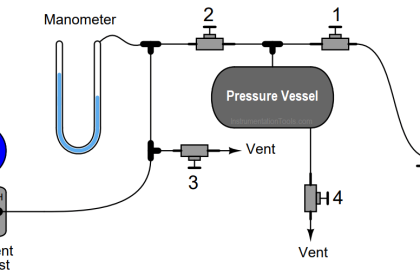
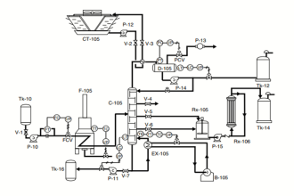
This Honeywell model UDC2500 controller needs to connect to a loop-powered pressure transmitter in such a way that it displays the amount of pressure in the process vessel, and outputs a signal to the 120 VAC alarm lamp if the process pressure becomes too great/high.
Alarm relay #1 in the controller has been configured for a high-pressure trip point of 140 PSI:
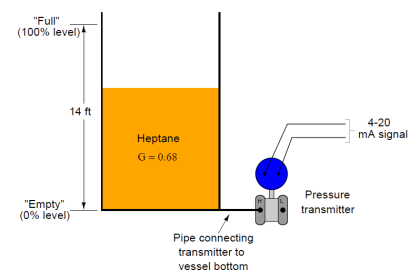
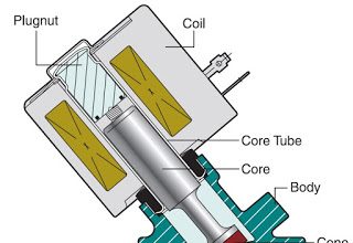
Loop Powered Pressure Transmitter
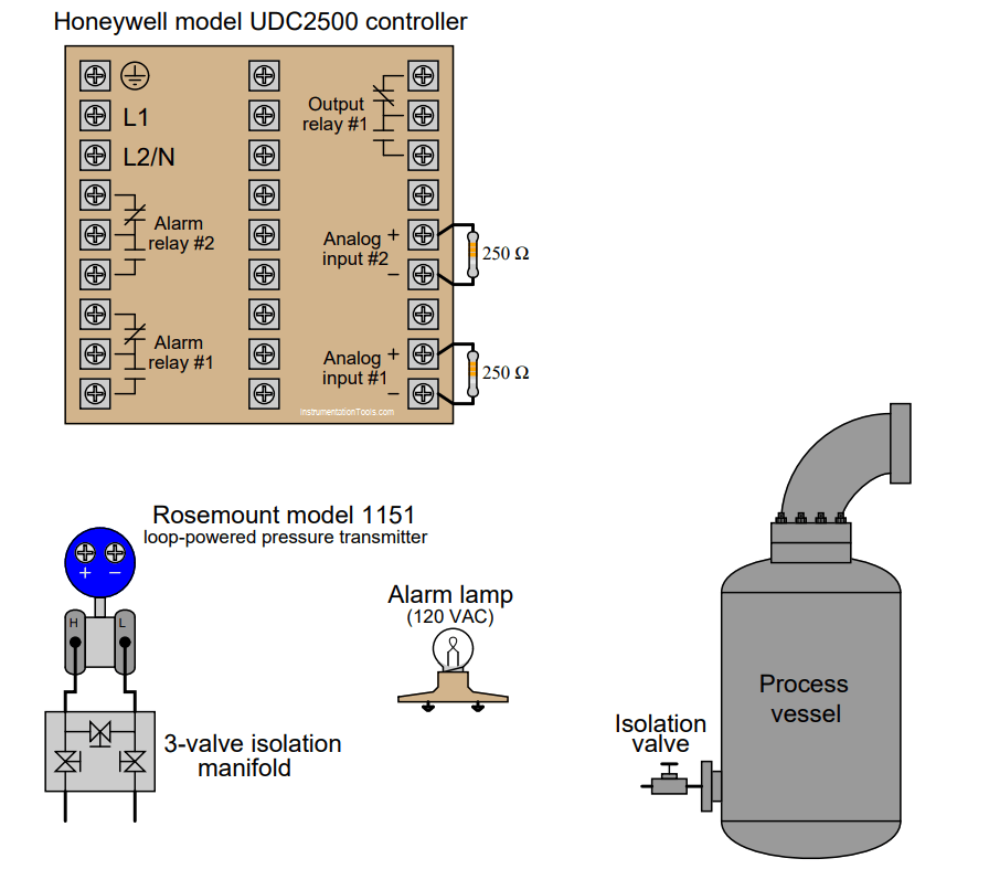
Sketch all necessary connecting wires and tubes to make this a working system. Note: you will need to add electrical power sources to the diagram!
Also, identify the proper open/closed state for each hand valve contained in the pressure transmitter’s three-valve isolation manifold.
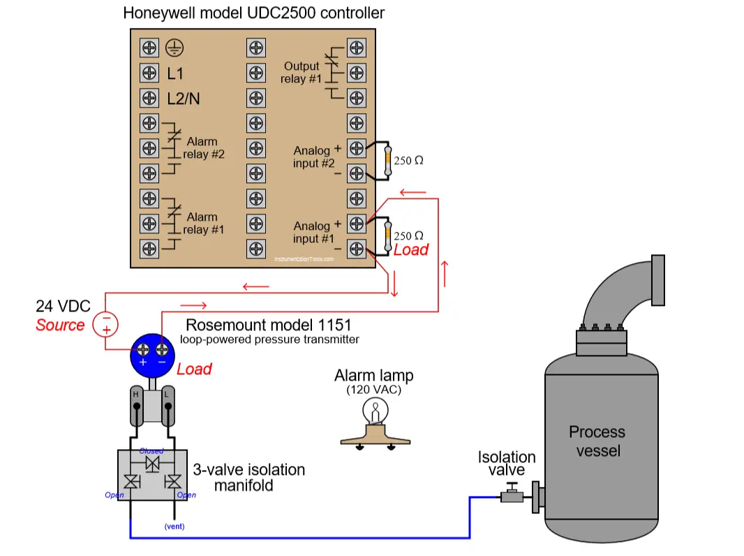
Solution:
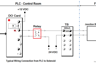
The below figure shows you the connections for the pressure transmitter and a external source.
Share with you how do you cannect the alarm lamp?
More Questions:
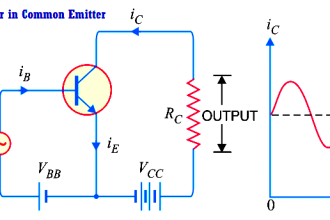
1. A problem-solving technique useful for making proper connections in pictorial circuit diagrams is to first identify the directions of all DC currents entering and exiting component terminals, as well as the respective voltage polarity marks (+,−) for those terminals, based on your knowledge of each component acting either as an electrical source or an electrical load.
Discuss and compare how these arrows and polarity marks (refer above picture) simplify the task of properly connecting wires between components.
2. Supposing the transmitter outputs a current value of 14 mA, calculate all voltage drops in this circuit.
3. The pressure transmitter configured 0 to 10 bar range. What is the pressure reading of transmitter when the loop-current is 11mA?
4. The pressure transmitter displays a reading of 3.5 bar. What is the loop-current?
Share your answers with us through below comments section.
Read Next:
- Level Control using Flow Loop
- Question on Analytical Controller
- Digital to Analog Conversion
- Differential Pressure Transmitter
- Pressure Transmitter Circuit
Credits: Tony R. Kuphaldt