Inst ToolsInst ToolsInst Tools
  • Courses
  • Automation
    • PLC
    • Control System
    • Safety System
    • Communication
    • Fire & Gas System
  • Instrumentation
    • Design
    • Pressure
    • Temperature
    • Flow
    • Level
    • Vibration
    • Analyzer
    • Control Valve
    • Switch
    • Calibration
    • Standards
    • Basics
    • Formula
    • Erection & Commissioning
    • Process Fundamentals
    • Root Cause Analysis
  • Interview
    • Instrumentation
    • Electrical
    • Electronics
    • Practical
  • Q&A
    • Instrumentation
    • Control System
    • Electrical
    • Electronics
    • Analog Electronics
    • Digital Electronics
    • Power Electronics
    • Microprocessor
Search
  • Courses
  • PLC
  • Control Systems
All rights reserved. Reproduction in whole or in part without written permission is prohibited.
Reading: How to do Force in GE PLC Proficy Machine Edition?
Share
Notification Show More
Font ResizerAa
Inst ToolsInst Tools
Font ResizerAa
  • Courses
  • PLC
  • Control Systems
Search
  • Courses
  • Automation
    • PLC
    • Control System
    • Safety System
    • Communication
    • Fire & Gas System
  • Instrumentation
    • Design
    • Pressure
    • Temperature
    • Flow
    • Level
    • Vibration
    • Analyzer
    • Control Valve
    • Switch
    • Calibration
    • Standards
    • Basics
    • Formula
    • Erection & Commissioning
    • Process Fundamentals
    • Root Cause Analysis
  • Interview
    • Instrumentation
    • Electrical
    • Electronics
    • Practical
  • Q&A
    • Instrumentation
    • Control System
    • Electrical
    • Electronics
    • Analog Electronics
    • Digital Electronics
    • Power Electronics
    • Microprocessor
Follow US
All rights reserved. Reproduction in whole or in part without written permission is prohibited.
Inst Tools > Blog > PLC Tutorials > How to do Force in GE PLC Proficy Machine Edition?

How to do Force in GE PLC Proficy Machine Edition?

Last updated: March 4, 2021 12:40 pm
Editorial Staff
PLC Tutorials
1 Comment
Share
5 Min Read
SHARE

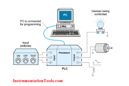
Learn how to do Force ON and Force OFF in GE PLC software proficy machine edition using ladder logics and reference view tables.

FORCE in GE PLC

Step 1:

Open “Proficy Machine Edition” Software

Open "Proficy Machine Edition" Software

Step 2:

Open the saved project.

Proficy Machine Edition

Step 3:

Software loaded.

GE Proficy Software

Step 4:

First Click on Online mode then click on Toggle online. Refer the below picture.

Proficy Online mode then click on Toggle online

Step 5:

Now you are online. Browse the logic and select the required variable to be forced.

Right-click on the variable to be forced and click “Force ON” option as shown in the below figure.

Here we are forcing a on/off valve or also called as shutdown valve. Force ON means we are making the logic status to 1.

Force ON in Proficy Machine Edition

Step 6:

Now if we want to test the logic status with “0” then right-click on the required variable and click “Force OFF” as shown in the below figure.

Force OFF means we are making the logic status to 0.

Force OFF in Proficy Machine Edition

Step 7:

After testing the logic with Force ON and Force OFF options, we must remove the force so the logic will work in real-time otherwise these variables will stay in force state.

Right-click on the required variable and select “Remove Force” option as shown in the below figure.

Remove Force in Proficy Machine Edition

Step 8:

Till now we discussed how to do force ON and OFF from logics.

Now if we want to do the force ON and OFF from reference tables then the below steps will apply.

Select the “Reference View Tables” menu in the left side-bar and expand it.

Reference View Tables

Step 9:

Select the “Default Tables” folder in the left side-bar and expand it as shown in the below figure.

Reference View Tables in GE PLC

Step 10:

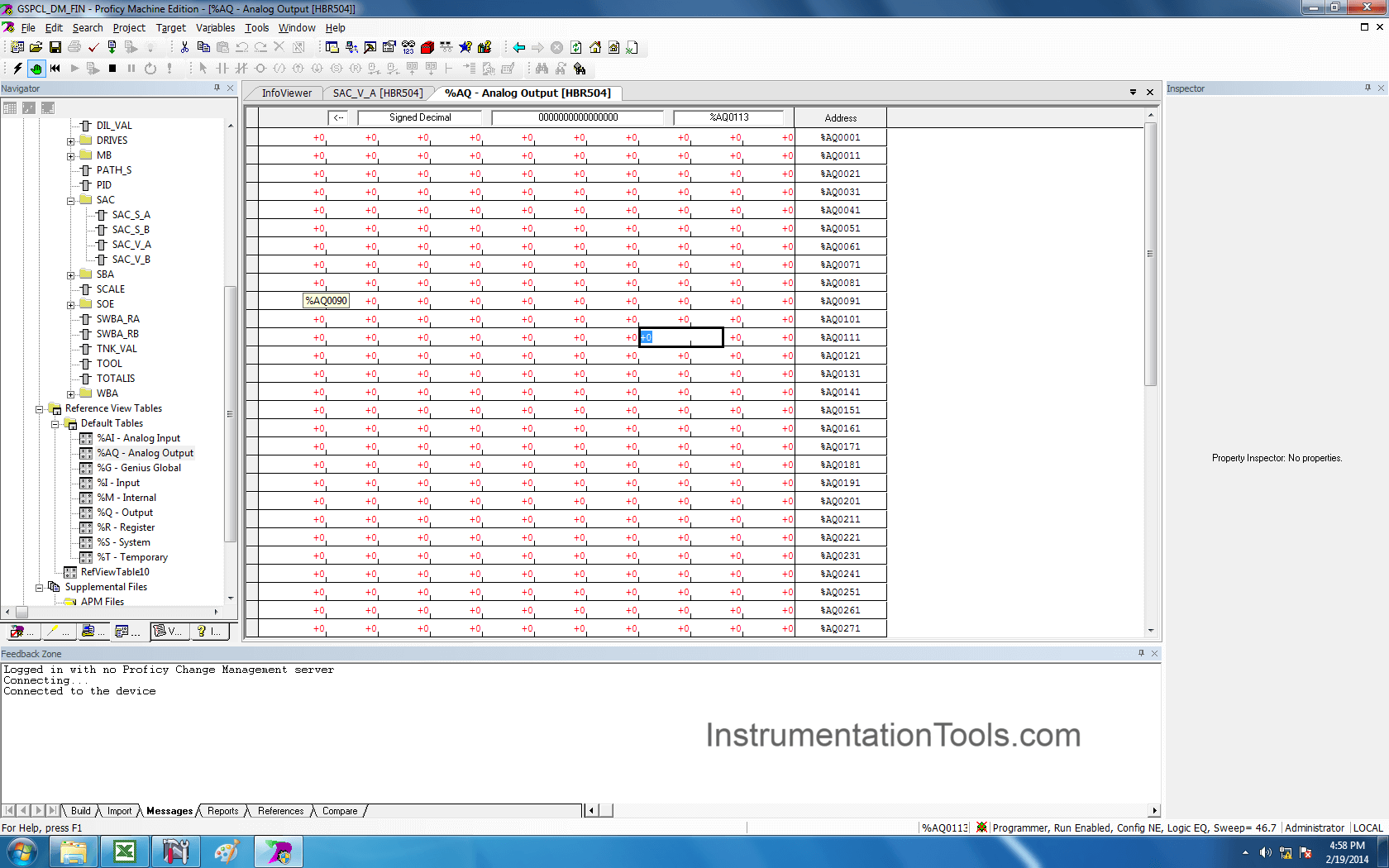
Select “Analog Output” option in the left side-bar and double-click on it.

In this window, we must know the address used for the outputs in the logic.

Select the required address (%AQ0113 in our example), click on it and apply the required value.

Analog Output Force in PLC

Step 11:

After testing, again enter the default value.

Force in PLC

Step 12:

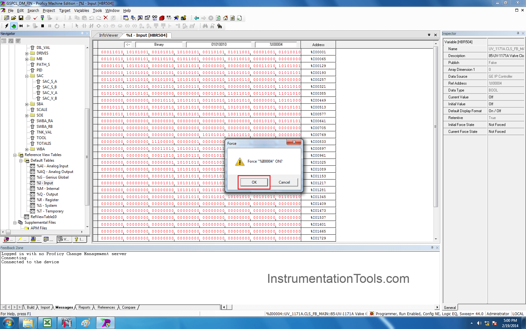
Now we see the FORCE ON and FORCE OFF of digital inputs.

Select the “Input” option in the left side-bar as shown in the below figure.

FORCE ON and FORCE OFF of digital inputs

Step 13:

In our example, we want to force %I00005 address. Select the respective bit and right-click on it.

The value in the selected address if logic “0”.

A drop-down window will appear as shown in the below figure and select “Force ON” option.

Force ON Digital Inputs in PLC

Step 14:

Then a pop-up window will open for confirmation. Click on “OK”.

Force ON Digital Inputs

Step 15:

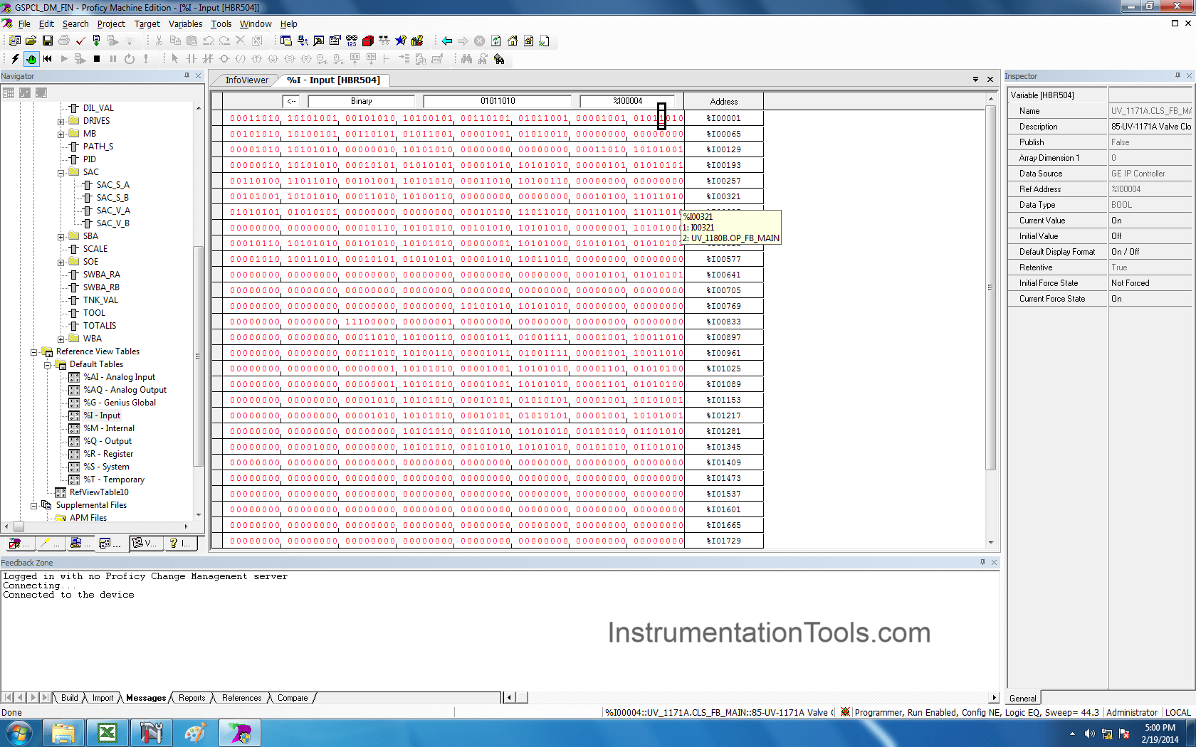
As we used FORCE ON option, so the logical value in the address %I00005 will change to logic “1” as shown in the below figure.

Force PLC

Step 16:

Similarly, right-click on the address and click on “Force OFF” option to make the logic status to “0”.

Force OFF Digital Inputs in PLC

Step 17:

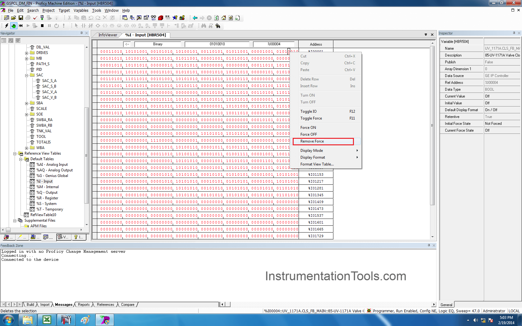
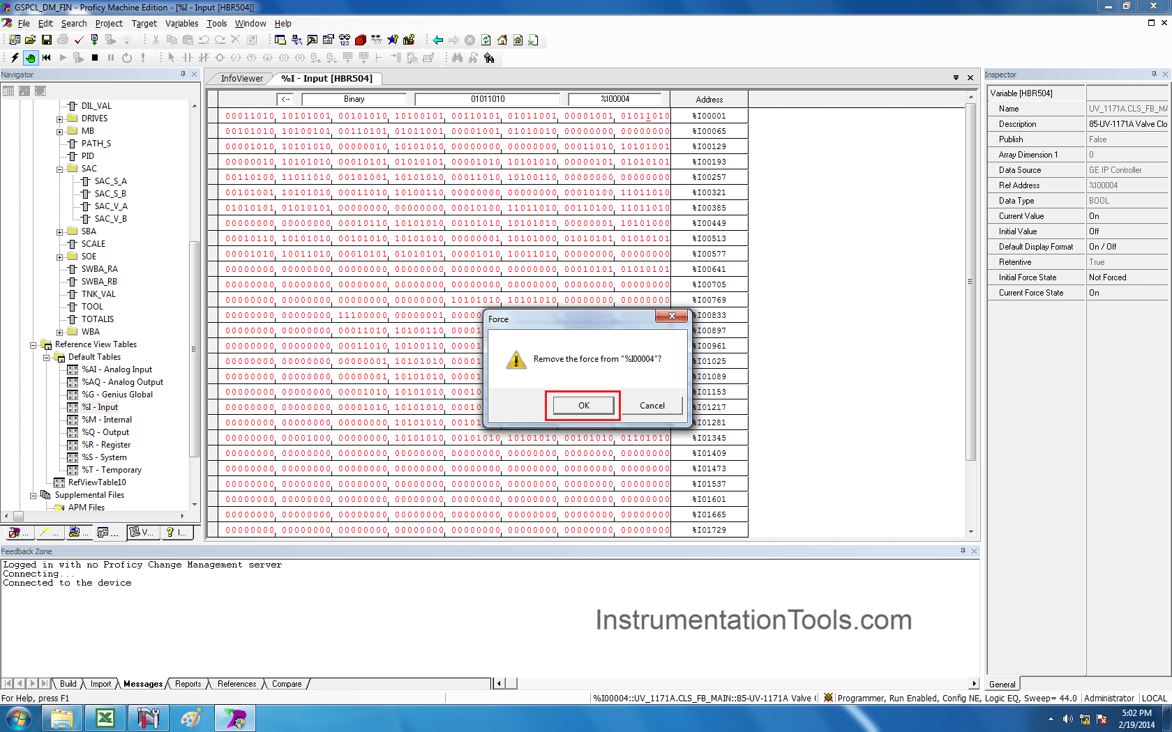
After testing, we have to remove the force otherwise the logic status will stay in the forced state.

So, right-click on the required address and select “Remove Force” option.

Remove Force Digital Inputs in PLC

Step 18:

Again, a pop-window will open for confirmation. Click on “OK” to remove the force.

Force Inputs in PLC

Step 19:

Now if we want to show all the variables which are in “Forced state” then follow the below step.

Select “HBR504” option and right-click on it.

A drop-down window will appear, now select “online Commands”, again a new dropdown appears.

Select “Show Forces in Controller” option as shown in the below figure.

Show Forces in PLC Controller

Step 20:

Now software displays all the forced variables in the controller as shown in the below figure.

How to do Force ON and OFF in GE Proficy Machine Edition?

If you liked this article, then please subscribe to our YouTube Channel for PLC and SCADA video tutorials.

You can also follow us on Facebook and Twitter to receive daily updates.

Read Next:

  • Download Free PLC software
  • SCADA Software Demo
  • Up Down Counter in PLC
  • Grounding Scheme in PLC
  • Backup from Siemens PLC
  • Wiring Diagrams of PLC
Don't Miss Our Updates
Be the first to get exclusive content straight to your email.
We promise not to spam you. You can unsubscribe at any time.
Invalid email address
You've successfully subscribed !

Continue Reading

PLC Analog Signals Wiring Techniques
Electric Motor Forward Reverse with Repeat Cycle PLC Logic
What is a Watchdog Timer in PLC?
Shutdown Motors in Timed Operation PLC Program
What is Function Module in Siemens PLC?
How to Use the Shift and Rotate Instructions in PLC?
Share This Article
Facebook Whatsapp Whatsapp LinkedIn Copy Link
Share
1 Comment
  • R Gupta says:
    September 26, 2020 at 6:02 pm

    Why are we using “toggle online” after taking PLC online in step 4?

    Reply

Leave a Reply Cancel reply

Your email address will not be published. Required fields are marked *

Stay Connected

128.3kFollowersLike
69.1kFollowersFollow
208kSubscribersSubscribe
38kFollowersFollow

Categories

Explore More

Automatic Curtain Control – PLC Programming Solution
How to Wire a Field instrument to Control Room with Example
PLC Program for Washing Machine
Batch Simulator PLC Example Program using LogixPro Simulator
What is a GSD File and Why it is required?
Ladder Logic MCQ Questions and Answers
How to use Master Control Reset (MCR) Instruction in PLC
Example of Flip-Flop PLC Program for Lamps Application

Keep Learning

Allen Bradley PLC Example with Sub routines

How to use Sub Routines with Allen Bradley PLC

Instrumentation Engineer in Process Plant Project

Instrumentation Engineer in Process Plant Project

Why Are Charcoal and Salt Added to an Earthing Pit

Why Are Charcoal and Salt Added to an Earthing Pit?

Distributed IO for Siemens PLC

How to Configure Distributed IO in a PLC Project?

Allen-Bradley PLC Program

Troubleshoot Allen Bradley PLC Logic

Ladder Logic Example of Two Motors

Ladder Logic Example of Two Motors Interlinked with another Motor

Parking Garage Indicator PLC Automation

Parking Garage Indicator: PLC Automation System

Wonderware Recipe Manager Plus

What is Recipe Management in SCADA?

Learn More

Control Valves Leak Tightness

Control Valves Leak Tightness Restoration Pose Difficulties

Historical Scada graph

Configuration of InTouch Scada Trends

Current to Pressure Converter Principle

Current to Pressure (I/P) Converter Principle

Kiln

Kiln Inlet Gas Analyzer

Digital Electronics Multiple Choice Questions

Erasable Programmable Read Only Memory Objective Questions

multiphase-flowmeter-working-principle

What are Multiphase Flow Meters? – Working Principle, Advantages

Shaft and Coupling Bore Tapers Repair Caused Frequent Shutdowns

Shaft and Coupling Bore Tapers Repair Caused Frequent Shutdowns

Transistor Failure Rate Calculation

Transistor Failure Rate Calculation

Follow US
All rights reserved. Reproduction in whole or in part without written permission is prohibited.
Welcome Back!

Sign in to your account

Username or Email Address
Password

Lost your password?