Inst ToolsInst ToolsInst Tools
  • Courses
  • Automation
    • PLC
    • Control System
    • Safety System
    • Communication
    • Fire & Gas System
  • Instrumentation
    • Design
    • Pressure
    • Temperature
    • Flow
    • Level
    • Vibration
    • Analyzer
    • Control Valve
    • Switch
    • Calibration
    • Erection & Commissioning
  • Interview
    • Instrumentation
    • Electrical
    • Electronics
    • Practical
  • Q&A
    • Instrumentation
    • Control System
    • Electrical
    • Electronics
    • Analog Electronics
    • Digital Electronics
    • Power Electronics
    • Microprocessor
Search
  • Books
  • Software
  • Projects
  • Process
  • Tools
  • Basics
  • Formula
  • Power Plant
  • Root Cause Analysis
  • Electrical Basics
  • Animation
  • Standards
  • 4-20 mA Course
  • Siemens PLC Course
Reading: Zero Suppression and Zero Elevation Calculations
Share
Notification Show More
Font ResizerAa
Inst ToolsInst Tools
Font ResizerAa
  • Courses
  • Design
  • PLC
  • Interview
  • Control System
Search
  • Courses
  • Automation
    • PLC
    • Control System
    • Safety System
    • Communication
    • Fire & Gas System
  • Instrumentation
    • Design
    • Pressure
    • Temperature
    • Flow
    • Level
    • Vibration
    • Analyzer
    • Control Valve
    • Switch
    • Calibration
    • Erection & Commissioning
  • Interview
    • Instrumentation
    • Electrical
    • Electronics
    • Practical
  • Q&A
    • Instrumentation
    • Control System
    • Electrical
    • Electronics
    • Analog Electronics
    • Digital Electronics
    • Power Electronics
    • Microprocessor
Follow US
All rights reserved. Reproduction in whole or in part without written permission is prohibited.
Inst Tools > Blog > Formulas > Zero Suppression and Zero Elevation Calculations

Zero Suppression and Zero Elevation Calculations

Last updated: April 19, 2019 3:18 pm
Editorial Staff
Formulas Level Measurement
10 Comments
Share
5 Min Read
SHARE

This article provides information on Zero Suppression and Zero Elevation Calculations used in differential pressure level transmitter.

Contents
What is Zero Suppression ?What is Zero Elevation ?Zero Suppression and Zero Elevation Example CalculationZero suppression calculationZero elevation calculation Closed Tank With Wet Leg

What is Zero Suppression ?

In some cases, the level transmitter has to be mounted X meters below the base of an open tank as shown in below figure.
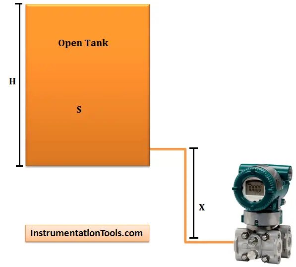
Zero Suppression in level Measurement

The liquid in the high pressure impulse line exerts a constant pressure (P = S . X) on the high pressure side.

That is, the pressure on the high pressure side of the DP Transmitter is always higher than the actual pressure exerted by the liquid column in the tank by (SG . X) – so the reading will be in error high.

This constant pressure would cause an output signal that is higher than 4 mA when the tank is empty and above 20 mA when it is full.

When the liquid level is at H meters, pressure on the high pressure side of the transmitter will be:

Phigh = S·H + S.X + Patm

Plow= Patm

ΔP = Phigh – Plow = S . H + S . X

The transmitter has to be negatively biased by a value of S.X so that the output of the transmitter is proportional to the tank level (S . H) only.

The above procedure is called Zero Suppression and it can be done during calibration of the transmitter.

What is Zero Elevation ?

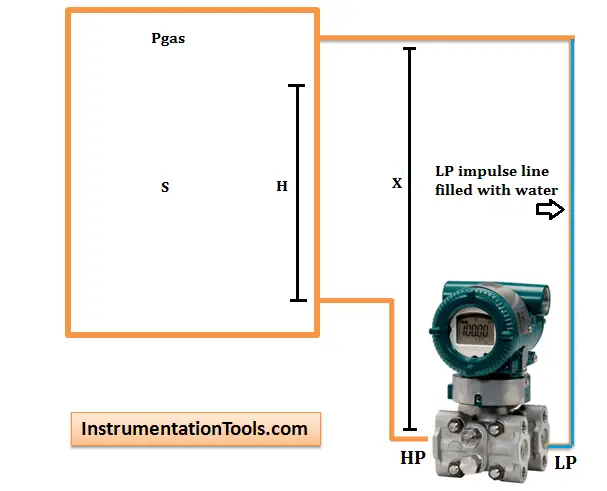
When a wet leg installation is used,the low pressure side of the level transmitter will always experience a higher hydrostatic pressure than the high pressure side.

This is due to the fact that the height of the wet leg (X) is always just greater than the maximum height of the liquid column (H) inside the tank.

Zero Elevation in level measurement

When the liquid level is at H meters, we have:

Phigh =Pgas + S . H

Plow =Pgas + S . X

ΔP = Phigh – Plow = S . H – S . X = -S(X . H)

The differential pressure ΔP sensed by the transmitter is always a negative value (i.e. the low pressure side has a higher pressure than high pressure side).

To properly calibrate the transmitter, a positive bias (S . X) is needed to elevate the transmitter output.

This positive biasing technique is called zero elevation.

Zero Suppression and Zero Elevation Example Calculation

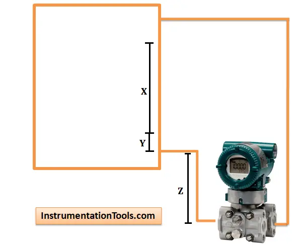
Zero suppression calculation

Zero suppression calculation in Level Measurement

Span = (x) (GL)

HW at minimum level = (z) (GS) + (y) (GL)

HW at maximum level = (z) (GS) + (x + y) (GL)

Where
GL = Specific gravity of tank liquid
GS = Specific gravity of seal liquid
HW = Equivalent head of water

x, y, and z as shown in above figure

Example:

Open tank with x = 80 inches

y = 5 inches

z = 10 inches
GL = 0.8
GS = 0.9

Span = (80)(0.8) = 64 inches

HW at minimum level = (10)(0.9) + (5)(0.8) = 13 inches

HW at maximum level = (10)(0.9) + (5 + 80)(0.8) = 77 inches

Calibrated Range = 13 to 77 inches head of water

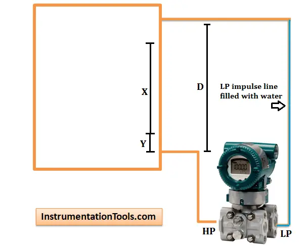
Zero elevation calculation Closed Tank With Wet Leg

Zero elevation calculation Closed Tank With Wet Leg

Span = (x)(GL) Wet Leg

HW at minimum level = (y)(GL) – (d)(GS)

HW at maximum level = (x + y)(GL) – (d)(GS)

Where
GL = Specific gravity of tank liquid
GS = Specific gravity of seal liquid
HW = Equivalent head of water

Example:

Closed tank with x = 70 inches y = 20 inches, and d = 100 inches,  GL = 0.8 Seal Liquid,  GS = 0.9

Span = (70)(0.8) = 56 inches

HW at minimum level = (20)(0.8) – (100)(0.9) = -74 inches

HW at maximum level = (70 + 20)(0.8) – (100)(0.9) = -18 inches

Calibrated Range = -74 to -18 inches head of water

(Minus signs indicate that the higher pressure is applied to the low pressure side of the transmitter.)

Articles You May Like :

Level Transmitter Compensation

Field Instrumentation Questions

DP Type Level Measurement

Fork Level Switches Principle

Remote mount Level Transmitter
Don't Miss Our Updates
Be the first to get exclusive content straight to your email.
We promise not to spam you. You can unsubscribe at any time.
Invalid email address
You've successfully subscribed !

Continue Reading

Calculate Temperature Coefficient of RTD
Closed Tank Remote Seal Capillary type DP Transmitter
Bubbler Liquid Level Transmitter Calculation
4-20mA Linear Conversion Calculation for VFD Drive (Formula)
Formula for Linear mA to Square root mA conversion
Displacer Level Transmitter 5-point Calibration
Share This Article
Facebook Whatsapp Whatsapp LinkedIn Copy Link
Share
10 Comments
  • Karuna says:
    May 6, 2016 at 1:35 am

    . I am very thankful to you sir. Thanks for explaining about Zero Suppression and Zero Elevation.

    Reply
  • Bob Swan says:
    June 21, 2016 at 11:27 am

    How about explaining how to calculate zero suppression and zero elevation when the level transmitter is above a closed tank and the upper head space is pressurized at 30 psig with air? This is one of the common uses for remote water level monitoring of the seal pots/tanks for the process pump seals.

    Reply
  • AKHILBALAN says:
    July 27, 2016 at 3:05 pm

    Thanks sir

    Reply
  • Abdullah Khan says:
    August 14, 2016 at 11:58 am

    Thank you Sir for all your best Information to sharing us

    Reply
  • Rajesh sonagara says:
    December 22, 2016 at 6:32 am

    Thanks you sir

    Reply
  • Mdnazir says:
    March 20, 2017 at 4:24 pm

    Why we used upperline high in drum level or dearetor level

    Reply
  • ZamraMokhtar says:
    April 19, 2017 at 6:50 pm

    Thannks for refreshing the theory

    Reply
  • Hariharan says:
    April 16, 2020 at 10:13 pm

    What is Zero Elevation?
    The H in the related figure is wrong from the formula Phigh =Pgas + S . H.
    As per the formula H base line should be from the Transmitter datum line,( NOT from the tank bottom).

    Reply
  • Boopathi says:
    August 23, 2021 at 1:41 pm

    Kindly clarify some one how y came here, how y came and previous level calculation is differ kindly tell me.

    Reply
  • ALI ASAD says:
    December 5, 2022 at 12:10 am

    Thank you so much for explaining this topic,this is very beneficial article for learning.

    Reply

Leave a Reply Cancel reply

Your email address will not be published. Required fields are marked *

Stay Connected

128.3kFollowersLike
69.1kFollowersFollow
208kSubscribersSubscribe
38kFollowersFollow

Categories

Explore More

Questions on Level Switches
Hydrostatic Interface Level Measurement
Cable Float Level Switch Working Principle
Level Indicators Working Principle
Guided-Wave Radar Instruments Diagnostics
Micro-impulse Level Transmitter Principle
How to do 4-20mA Conversions Easily
Calculate Temperature Transmitter Output

Keep Learning

Asymmetric capillary for Level Measurement

Effects of Symmetric and Asymmetric Capillary Tube Pressure Measurement

Microwave Barrier Level Switch Working Principle

4-20 mA Conversion Formulas

Standard 4 to 20 mA Conversion Formula

DP-Transmitter-with-two-seals

DP Transmitter with Two Seals applications

Elevated Span and Suppressed Span

DP Level Transmitter Elevation and Suppression Corrections

DP Transmitter Level Measurement for Closed Tank Wet leg Method

DP Transmitter Dry Leg & Wet Leg Calculations

Practical Level Sensors Questions and Answers

Practical Level Sensors Questions and Answers

Rotary Level Switch Working Principle Animation

Rotary Level Switch Working principle Animation

Learn More

Electropneumatic Valve Positioner Working Principle

Electro Pneumatic Valve Positioner Schematic & Principle

statuses of all lamps and relay coils in the circuit

Analyze the Relay Circuit and Find the Status ?

Bias in Proportional Controller

Why Bias used in Proportional Controller ?

Control Valve Parts

Control Valve Parts Questions and Answers

What is Electrical Busbar

What is Electrical Busbar? Types, Advantages, Disadvantages

DP Transmitter Level Measurement for Closed Tank Wet leg Method

DP Transmitter Dry Leg & Wet Leg Calculations

Pulse Timer Instruction in PLC Programming

Pulse Timer Instruction in PLC Programming

Stepper Motor Parts

Stepper Motor MCQ

Follow US
All rights reserved. Reproduction in whole or in part without written permission is prohibited.
Welcome Back!

Sign in to your account

Username or Email Address
Password

Lost your password?