Inst ToolsInst ToolsInst Tools
  • Courses
  • Automation
    • PLC
    • Control System
    • Safety System
    • Communication
    • Fire & Gas System
  • Instrumentation
    • Design
    • Pressure
    • Temperature
    • Flow
    • Level
    • Vibration
    • Analyzer
    • Control Valve
    • Switch
    • Calibration
    • Erection & Commissioning
  • Interview
    • Instrumentation
    • Electrical
    • Electronics
    • Practical
  • Q&A
    • Instrumentation
    • Control System
    • Electrical
    • Electronics
    • Analog Electronics
    • Digital Electronics
    • Power Electronics
    • Microprocessor
Search
  • Books
  • Software
  • Projects
  • Process
  • Tools
  • Basics
  • Formula
  • Power Plant
  • Root Cause Analysis
  • Electrical Basics
  • Animation
  • Standards
  • 4-20 mA Course
  • Siemens PLC Course
Reading: Liquid Level Switch Control Pump and Lamp
Share
Notification Show More
Font ResizerAa
Inst ToolsInst Tools
Font ResizerAa
  • Courses
  • Design
  • PLC
  • Interview
  • Control System
Search
  • Courses
  • Automation
    • PLC
    • Control System
    • Safety System
    • Communication
    • Fire & Gas System
  • Instrumentation
    • Design
    • Pressure
    • Temperature
    • Flow
    • Level
    • Vibration
    • Analyzer
    • Control Valve
    • Switch
    • Calibration
    • Erection & Commissioning
  • Interview
    • Instrumentation
    • Electrical
    • Electronics
    • Practical
  • Q&A
    • Instrumentation
    • Control System
    • Electrical
    • Electronics
    • Analog Electronics
    • Digital Electronics
    • Power Electronics
    • Microprocessor
Follow US
All rights reserved. Reproduction in whole or in part without written permission is prohibited.
Inst Tools > Blog > Control Systems > Liquid Level Switch Control Pump and Lamp

Liquid Level Switch Control Pump and Lamp

Last updated: February 2, 2020 10:41 pm
Editorial Staff
Control Systems
No Comments
Share
4 Min Read
SHARE

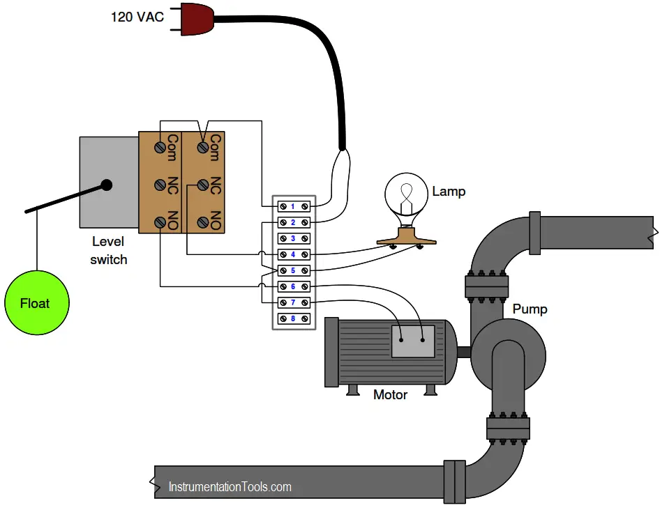
This pictorial diagram shows how a liquid level switch (with two separate SPDT switch units actuated by a common float mechanism) is wired to control both an electric pump and a lamp:

Liquid Level Switch

Liquid Level Switch Control Pump and Lamp

Under what liquid level condition will the lamp energize?

Under what liquid level condition will the pump motor energize?

Determine what an AC voltmeter would register under the following conditions:

→ Connected between terminals 1 and 2; high liquid level

→ Connected between terminals 2 and 6; low liquid level

→ Connected between terminals 4 and 7; low liquid level

→ Connected between terminals 1 and 6; high liquid level

Supposing the pump motor refused to energize but the lamp still functioned properly (turning on and off when it should), devise a series of diagnostic tests you could implement with an AC voltmeter to locate the fault. For each test, explain what the result of that test means for your diagnosis of the problem.

Solution:

The lamp receives power through an NC (normally-closed) switch contact, which means it will be energized when the level switch is in the resting (low level) state.

The pump motor receives power through a NO (normally-open) switch contact, which means it will be energized when the level switch is in the actuated (high level) state.

Determine what an AC voltmeter would register under the following conditions:

→ Connected between terminals 1 and 2; high liquid level – 120 VAC regardless of the level

→ Connected between terminals 2 and 6; low liquid level – 0 VAC

→ Connected between terminals 4 and 7; low liquid level – 120 VAC

→ Connected between terminals 1 and 6; high liquid level – 0 VAC

The symptoms tell us the problem must be limited to the pump circuit, and cannot be related to anything common with both the pump and lamp because the lamp still works as it should.

Taking a voltage measurement between terminals 6 and 7 while the liquid is at a high level is a good first step: the presence of 120 VAC between those points would indicate the switch is closing at it should, and that there must be an open fault between those terminals and the motor (including possibly within the motor itself ).

The lack of voltage between those points during a high liquid level would indicate an open fault between those terminals the source.

Here are some indeterminate tests. For each one, challenge engineers to explain why the specified test would not give good diagnostic information:

Measuring voltage between terminals 1 and 2 (We already know there is the supply voltage, since the lamp works)

Measuring voltage between terminals 6 and 7 while the liquid level is low (it is impossible for any fault prohibiting motor function to yield anything but zero volts in a condition of low level, and therefore this test tells us nothing about the problem).

Credits: Tony R. Kuphaldt

Read Next:

  • Level Switch Control Logic
  • Need for Automatic Controls
  • Level Measurement Basics
  • What is Reflex Level Gauge?
  • Displacer Level Sensor Principle
Don't Miss Our Updates
Be the first to get exclusive content straight to your email.
We promise not to spam you. You can unsubscribe at any time.
Invalid email address
You've successfully subscribed !

Continue Reading

How-to Create Instrument Loop Diagram (ILD)?
Integral (Reset) Control Theory
What is Data Acquisition? – Elements and Components
PID Controller Loop Tuning Tips
PID Controller Loop Tuning Questions and Answers – Part 2
How to Select the Right Type of Controller
Share This Article
Facebook Whatsapp Whatsapp LinkedIn Copy Link
Share
Leave a Comment

Leave a Reply Cancel reply

Your email address will not be published. Required fields are marked *

Stay Connected

128.3kFollowersLike
69.1kFollowersFollow
210kSubscribersSubscribe
38kFollowersFollow

Categories

Explore More

PLC, DCS, and ESD Marshalling Cabinet Checks
Limit Controls : High Limit & Low Limit Functions
Design Logic Diagrams with Standard Formats for Process Control
Difference Between Serial and Parallel Communication
Feedforward Control Principle
The need for automatic controls
Sink or Source? Normally Open or Normally Closed?
Pressure Control System Problems

Keep Learning

What is a Network Switch?

Network Switch Requirement in SCADA and DCS Architecture

Fundamental Motion Control Commands

Fundamental Motion Control Commands

Difference between ON-OFF Controller and PID Controller

Difference between ON-OFF Controller and PID Controller

Loop-powered 4-20 mA transmitter

Loop-powered 4-20 mA Transmitter Circuit Voltage drop

Junction Box Wiring

4-20mA Junction Box versus Fieldbus (FF) Junction Box

ICS System Design

ICS System Design Considerations

Python in Industrial Automation

Python in Industrial Automation and Control Systems

Drum water level control

Closed Loop Control System : Boiler Water Level Control System

Learn More

Rotary Equipment

Modern Engineering Solutions for Rotary Equipment

Ratio Control Example

Ratio Controller Example

strain gauge changes as it stretches and shrinks

Why Strain Gauge Resistance Changes as it Stretches and Shrinks?

Faceplate in WinCC

Siemens HMI Training – Using UDTs with Faceplates

electromechanical-level-measurement-working-principle

ElectroMechanical Level Measurement Working Principle

Reed Switch Principle

Reed switch Working Principle

pH Analyzer Do’s and Don’ts

pH Analyzer Do’s and Don’ts

steadily pour a liquid into vertical tube

Vertical Tube Liquid Level Equilibrium

Menu

  • About
  • Privacy Policy
  • Copyright

Quick Links

  • Learn PLC
  • Helping Hand
  • Part Time Job

YouTube Subscribe

Follow US
All rights reserved. Reproduction in whole or in part without written permission is prohibited.
Welcome Back!

Sign in to your account

Username or Email Address
Password

Lost your password?