Inst ToolsInst ToolsInst Tools
  • Courses
  • Automation
    • PLC
    • Control System
    • Safety System
    • Communication
    • Fire & Gas System
  • Instrumentation
    • Design
    • Pressure
    • Temperature
    • Flow
    • Level
    • Vibration
    • Analyzer
    • Control Valve
    • Switch
    • Calibration
    • Erection & Commissioning
  • Interview
    • Instrumentation
    • Electrical
    • Electronics
    • Practical
  • Q&A
    • Instrumentation
    • Control System
    • Electrical
    • Electronics
    • Analog Electronics
    • Digital Electronics
    • Power Electronics
    • Microprocessor
  • Request
Search
  • Books
  • Software
  • Projects
  • Process
  • Tools
  • Basics
  • Formula
  • Power Plant
  • Root Cause Analysis
  • Electrical Basics
  • Animation
  • Standards
  • 4-20 mA Course
  • Siemens PLC Course
Reading: Effect of Tank Design on Accuracy of Level Measurement
Share
Notification Show More
Font ResizerAa
Inst ToolsInst Tools
Font ResizerAa
  • Courses
  • Design
  • PLC
  • Interview
  • Control System
Search
  • Courses
  • Automation
    • PLC
    • Control System
    • Safety System
    • Communication
    • Fire & Gas System
  • Instrumentation
    • Design
    • Pressure
    • Temperature
    • Flow
    • Level
    • Vibration
    • Analyzer
    • Control Valve
    • Switch
    • Calibration
    • Erection & Commissioning
  • Interview
    • Instrumentation
    • Electrical
    • Electronics
    • Practical
  • Q&A
    • Instrumentation
    • Control System
    • Electrical
    • Electronics
    • Analog Electronics
    • Digital Electronics
    • Power Electronics
    • Microprocessor
  • Request
Follow US
All rights reserved. Reproduction in whole or in part without written permission is prohibited.
Inst Tools > Blog > Level Measurement > Effect of Tank Design on Accuracy of Level Measurement

Effect of Tank Design on Accuracy of Level Measurement

Last updated: January 13, 2020 7:35 pm
Editorial Staff
Level Measurement
No Comments
Share
3 Min Read
SHARE

A journal article by FJ Berto states that a number of level measurement accuracy limitations in the use of manual and automatic tank gauging are presented in the API MPMS (American Petroleum Institute, Manual of Petroleum Measurement Standards).

The discussion presented treats the tank gauging system and the tank as the system, not just the instrumentation that performs the measurement. This introduces the idea of designing both components to be ‘as one’ in the same way, with a view to minimizing factors from each that can affect accuracy.

The limitations stated in API MPMS are:

  • Accuracy of the manual gauging tape or ATG;
  • Accuracy of the tank capacity table and the effect of tank tilt and hydrostatic pressure;
  • Shell expansion caused by the material contained;
  • Under-measurement as a result of the tank bottom shifting under load from its perceived position;
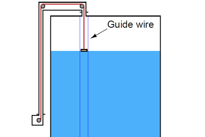
  • Movement of the gauging well. Excessive movement in the gauging well reduces capability for accurate level measurement. Guidance should be sought to install the gauging well to minimize any potential for gauging well movement;
  • Volume measurement accuracy is affected by the movement of the tanks datum plate;
  • Over-measurement can occur when heavy or waxy materials leave a solidified residue, known as encrustation;
  • Thermal effects such as expansion or contraction of the tank. For level-based measurement, as opposed to volume measurement, this can have a significant impact because an expanded tank may contain a greater volume of fuel at a specific mid-point than it would at the same midpoint when not expanded;
  • Human error. These are normally associated more with manual means of level measurement, and less so with ATG.

Berto’s article highlights that the accuracy of any method of level measurement or tank gauging can be significantly affected by the tank. Considerations such as the expansion and contraction of the tank under loading, how the bottom moves under load, and reaction to changes in temperature can all affect the dimensions of the tank.

The tank gauging system should be installed bearing in mind these physical factors of the tank, and where possible designing the installation to minimize the effects upon measurement by the tank.

Reference: Berto FJ (1997). Review of Tank Measurement Errors Reveals Techniques for Greater Accuracy. Oil and Gas Journal 1997, Volume 95, Issue 9, pp68-73

Don't Miss Our Updates
Be the first to get exclusive content straight to your email.
We promise not to spam you. You can unsubscribe at any time.
Invalid email address
You've successfully subscribed !

Continue Reading

Calibration of Displacer Level Transmitter
Non Contacting Radar Level Transmitter Animation
Nuclear Level Detectors Cascade or Master/Slave concept
DP Level Measurement Problems
Guided Wave Radar Level Sensor Pressure and Temperature Effects
Ultrasonic Level Transmitter Animation
Share This Article
Facebook Whatsapp Whatsapp LinkedIn Copy Link
Share
Leave a Comment

Leave a Reply Cancel reply

Your email address will not be published. Required fields are marked *

Stay Connected

128.3kFollowersLike
69.1kFollowersFollow
210kSubscribersSubscribe
38kFollowersFollow

Categories

Explore More

Hybrid Level Measurement Principle, Selection, Installation, Limitations and Calibration
Displacer Level Transmitter 5-point Calibration
Differential Pressure (DP) Level transmitter Installed Above Tapping Point
Purpose of Tank Gauging Level Measurement
DP Level Transmitter with Zero Suppression Calibration
Guided-wave Radar Level Measurement Animation
Ultrasonic Level Switch Working Principle
Which Instrument is at Fault in this System?

Keep Learning

Closed-tank-DP-Level-Transmitter-with-wet-leg-elevation-zero-direct-mount-Calibration

Closed tank DP Level Transmitter with wet leg elevation zero direct mount Calibration

Cable Float Level Switch Principle

Cable Float Level Switch Working Principle

Radiometric level Principle

Radiometric level measurement Working Principle

Level Transmitter Design

Level Transmitter and Level Gauge Design Tips

Level Sensors

Advantages & Disadvantages of Level Measurement Systems

Guided Wave Radar Questions and Answers

Guided Wave Radar Questions and Answers

Bubbler Level Measurement System

Bubbler Level Sensor

Hydrostatic pressure Measurement

Basics of Hydrostatic Level Measurement

Learn More

Allen Bradley PLC Interview Questions & Answers

Allen Bradley PLC Interview Questions and Answers

Power Electronics Objective Questions

1 Phase Voltage Source Inverter Quiz

Flow Transmitter Output Current Calculation

Calculate Flow Transmitter Output Current

The Role of CNC Machining in Electronics Manufacturing

The Role of CNC Machining in Electronics Manufacturing

Measuring temperature with RTD

How RTD Measuring the Temperature

Free Omron PLC Programming Course in HINDI

Free Omron PLC Programming Course in HINDI

How Buoyant Force instruments Works

How Buoyant Force instruments Works ?

Current Divider Rule

Current Divider Rule

Menu

  • About
  • Privacy Policy
  • Copyright

Quick Links

  • Learn PLC
  • Helping Hand
  • Part Time Job

YouTube Subscribe

Follow US
All rights reserved. Reproduction in whole or in part without written permission is prohibited.
Welcome Back!

Sign in to your account

Username or Email Address
Password

Lost your password?