Design a ladder logic for providing lubricant for the gear box before the lathe spindle starts to run which aims to ensure that the lube oil pump motor starts first and the main motor starts subsequently ?
- I0.0– START pushbutton to Start Oil Pump Motor
- I0.1– START pushbutton to Stop Main Motor
- I0.2– STOP pushbutton to Stop Oil Pump Motor
- I0.3– STOP pushbutton to Stop Main Motor
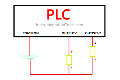
- Q0.0– Oil Pump Motor
- Q0.1– Main Motor
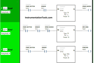
This program is a typical application of the conditional control circuit. Q0.0 is ON when Oil Pump START button is pressed. Therefore, the oil pump will start to provide lubricant for the gear box of main motor (Q0.1).
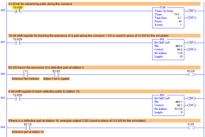
Ladder Logic for Lube Oil Pump

Under the precondition of the operating state of the Oil pump, the main motor (Q0.1) will be ON when the Main motor START button is pressed. During the operation of main motor (Q0.1), oil pump (Q0.0) needs to provide lubricant continuously.
The oil pump will be stopped when Oil pump STOP button I0.2 is activated, and the main motor will be stopped when Main motor STOP button I0.3 is activated.
NOTE :
In real time applications, we may use Time Delays before starting main motor. After starting the Lube Oil Pump, there will be certain time delay ( say 30 sec, 2 min, 5 min) provided to make sure the lube oil pressure is sufficient before running main motor. In some cases time delays also provided during stopping the motors, based on specific applications.
If you liked this article, then please subscribe to our YouTube Channel for PLC and SCADA video tutorials.
You can also follow us on Facebook and Twitter to receive daily updates.
Read Next:


Very nice…..
please give good notes about PLC ladder logic