A SCADA system performs four functions:
1. Data acquisition
2. Networked data communication
3. Data presentation
4. Control
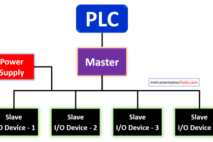
These functions are performed by four kinds of SCADA components:
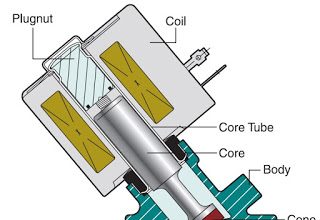
1. Sensors (either digital or analog) with control relays that directly interface with the managed system.
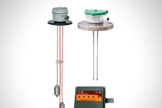
2. Remote telemetry units (RTUs). These are small computerized units deployed in the field at specific sites and locations. RTUs serve as local collection points for gathering reports from sensors and delivering commands to control relays.
3. SCADA master units. These are larger computer consoles that serve as the central processor for the SCADA system. Master units provide a human interface to the system and automatically regulate the managed system in response to sensor inputs.
4. Communications network that connects the SCADA master unit to the RTUs in the field.

Data Acquisition
First, the systems you need to monitor are much more complex than just one machine with one output. So a real-life SCADA system needs to monitor hundreds or thousands of sensors. Some sensors measure inputs into the system (for example, water flowing into a reservoir), and some sensors measure outputs (like valve pressure as water is released from the reservoir). Some of those sensors measure simple events that can be detected by a straightforward on/off switch, called a discrete input (or digital input).
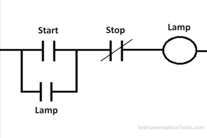
For example, in our simple model of the widget fabricator, the switch that turns on the light would be a discrete input. In real life, discrete inputs are used to measure simple states, like whether equipment is on or off, or tripwire alarms, like a power failure at a critical facility. Some sensors measure more complex situations where exact measurement is important.
These are analog sensors, which can detect continuous changes in a voltage or current input. Analog sensors are used to track fluid levels in tanks, voltage levels in batteries, temperature and other factors that can be measured in a continuous range of input. For most analog factors, there is a normal range defined by a bottom and top level.
For example, you may want the temperature in a server room to stay between 60 and 85 degrees Fahrenheit. If the temperature goes above or below this range, it will trigger a threshold alarm. In more advanced systems, there are four threshold alarms for analog sensors, defining Major Under, Minor Under, Minor Over and Major Over alarms.
Data Communication
In our simple model of the widget fabricator, the “network” is just the wire leading from the switch to the panel light. In real life, you want to be able to monitor multiple systems from a central location, so you need a communications network to transport all the data collected from your sensors.
Early SCADA networks communicated over radio, modem or dedicated serial lines. Today the trend is to put SCADA data on Ethernet and IP over SONET. For security reasons, SCADA data should be kept on closed LAN/WANs without exposing sensitive data to the open Internet. Real SCADA systems don’t communicate with just simple electrical signals, either.
SCADA data is encoded in protocol format. Older SCADA systems depended on closed proprietary protocols, but today the trend is to open, standard protocols and protocol mediation. Sensors and control relays are very simple electric devices that can’t generate or interpret protocol communication on their own.
Therefore the remote telemetry unit (RTU) is needed to provide an interface between the sensors and the SCADA network. The RTU encodes sensor inputs into protocol format and forwards them to the SCADA master; in turn, the RTU receives control commands in protocol format from the master and transmits electrical signals to the appropriate control relays.
Image courtesy : nelson electric service
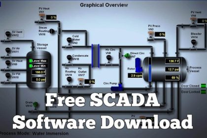
Data Presentation
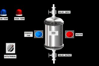
The only display element in our model SCADA system is the light that comes on when the switch is activated. This obviously won’t do on a large scale — you can’t track a lightboard of a thousand separate lights, and you don’t want to pay someone simply to watch a lightboard, either.
A real SCADA system reports to human operators over a specialized computer that is variously called a master station, an HMI (Human-Machine Interface) or an HCI (Human-Computer Interface). The SCADA master station has several different functions. The master continuously monitors all sensors and alerts the operator when there is an “alarm” — that is, when a control factor is operating outside what is defined as its normal operation.
The master presents a comprehensive view of the entire managed system, and presents more detail in response to user requests. The master also performs data processing on information gathered from sensors — it maintains report logs and summarizes historical trends.An advanced SCADA master can add a great deal of intelligence and automation to your systems management, making your job much easier.
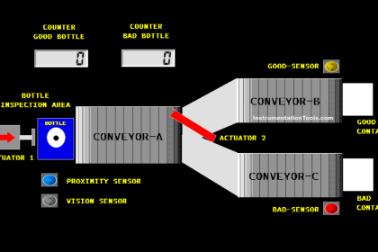
Control
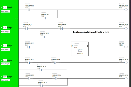
Unfortunately, our miniature SCADA system monitoring the widget fabricator doesn’t include any control elements. So let’s add one. Let’s say the human operator also has a button on his control panel. When he presses the button, it activates a switch on the widget fabricator that brings more widget parts into the fabricator.
Now let’s add the full computerized control of a SCADA master unit that controls the entire factory. You now have a control system that responds to inputs elsewhere in the system. If the machines that make widget parts break down, you can slow down or stop the widget fabricator. If the part fabricators are running efficiently, you can speed up the widget fabricator. If you have a sufficiently sophisticated master unit, these controls can run completely automatically, without the need for human intervention.
Of course, you can still manually override the automatic controls from the master station. In real life, SCADA systems automatically regulate all kinds of industrial processes.
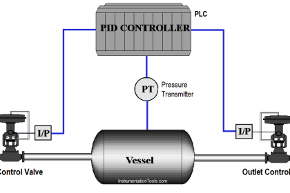
For example, if too much pressure is building up in a gas pipeline, the SCADA system can automatically open a release valve. Electricity production can be adjusted to meet demands on the power grid. Even these real-world examples are simplified; a full-scale SCADA system can adjust the managed system in response to multiple inputs.
If you liked this article, then please subscribe to our YouTube Channel for PLC and SCADA video tutorials.
You can also follow us on Facebook and Twitter to receive daily updates.
Read Next:


Nice
Great summary. Inst Tools has been useful resource, I use it frequently.