Self actuated pressure control valve do not depend on any external signal for pressure control. As the name suggests, pressure in the process line itself is used as an actuating signal to open or close the pressure control valve.
A self actuated pressure control valve can be used to control the pressure at either upstream or downstream of the control valve. If the pressure upstream to the valves is used to throttle the control valve, then the upstream pressure is maintained at a specified set point and such a valve is known as a backpressure control valve, as it maintains the backpressure imposed by the control valve.
If pressure at immediate downstream point of the valve is used as a signal to throttle the control valve, then the downstream pressure is maintained at a specified set point and such valves are known as self actuated pressure control valves.
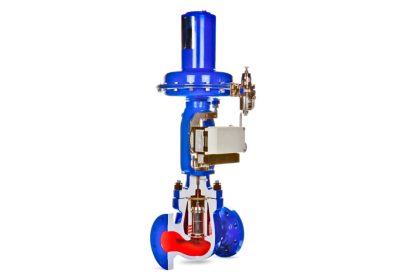
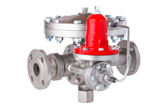
Self Actuated Pressure Control Valve
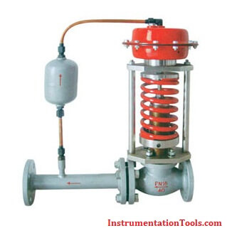
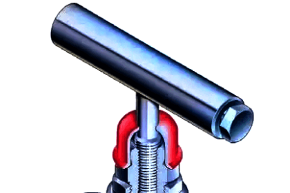
A self actuated pressure control valve uses a pitot tube which gives access for process fluid to pressurize the diaphragm which then acts to open the valve so process fluid from process line can pass through.
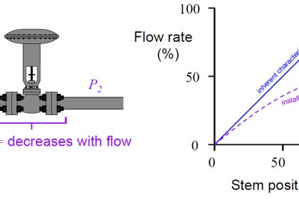
For a pressure regulator valve, pitot tube connects the diaphragm casing to a point downstream of control valve. When the pressure downstream to control valve increases beyond setpoint, process fluid exerts increased pressure on the diaphragm thus closing the valve. Closing of the valve stops process flow thus reducing the valve downstream pressure back to setpoint level.
When the pressure downstream of control valve drops below the setpoint level, process fluid from diaphragm casing recedes back to process line. This relieves pressure on diaphragm and opens the valve to allow increased process flow. Increased process flow leads to increase in pressure back to its setpoint.
For a back-pressure regulator valve, the pitot tube connects diaphragm casing to a point upstream of the pressure control valve and the process fluid from upstream point acts on the valve diaphragm to open or close the valve in case of high or low pressure respectively.


Can you send the catalog