Inst ToolsInst ToolsInst Tools
  • Courses
  • Automation
    • PLC
    • Control System
    • Safety System
    • Communication
    • Fire & Gas System
  • Instrumentation
    • Design
    • Pressure
    • Temperature
    • Flow
    • Level
    • Vibration
    • Analyzer
    • Control Valve
    • Switch
    • Calibration
    • Erection & Commissioning
  • Interview
    • Instrumentation
    • Electrical
    • Electronics
    • Practical
  • Q&A
    • Instrumentation
    • Control System
    • Electrical
    • Electronics
    • Analog Electronics
    • Digital Electronics
    • Power Electronics
    • Microprocessor
Search
  • Books
  • Software
  • Projects
  • Process
  • Tools
  • Basics
  • Formula
  • Power Plant
  • Root Cause Analysis
  • Electrical Basics
  • Animation
  • Standards
  • 4-20 mA Course
  • Siemens PLC Course
Reading: Calibration of Displacer Level Transmitter
Share
Notification Show More
Font ResizerAa
Inst ToolsInst Tools
Font ResizerAa
  • Courses
  • Design
  • PLC
  • Interview
  • Control System
Search
  • Courses
  • Automation
    • PLC
    • Control System
    • Safety System
    • Communication
    • Fire & Gas System
  • Instrumentation
    • Design
    • Pressure
    • Temperature
    • Flow
    • Level
    • Vibration
    • Analyzer
    • Control Valve
    • Switch
    • Calibration
    • Erection & Commissioning
  • Interview
    • Instrumentation
    • Electrical
    • Electronics
    • Practical
  • Q&A
    • Instrumentation
    • Control System
    • Electrical
    • Electronics
    • Analog Electronics
    • Digital Electronics
    • Power Electronics
    • Microprocessor
Follow US
All rights reserved. Reproduction in whole or in part without written permission is prohibited.
Inst Tools > Blog > Calibration > Calibration of Displacer Level Transmitter

Calibration of Displacer Level Transmitter

Last updated: May 27, 2019 4:17 pm
Editorial Staff
Calibration Level Measurement
14 Comments
Share
2 Min Read
SHARE

Calibration of Displacer Level Transmitter

Calibration Procedure of displacer type Level transmitter

Calibration Procedure:

*Ask panel man to put the controller in manual mode for control loop and to put it on MOS for ESD loop.
*Hook up HART Communicator and verify some parameters by refer to data sheet. Typical parameters are, tag number, PV, LRV and URV.
*Isolate the instrument from the process.
WARNING – If the process is hazardous, please ensure proper flushing is done to remove the entire hazard.
Remove isolation drain valve and open the vent flange
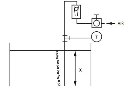
*Connect water pump to drain line and line up the reference tube
*Calculate the new measurement to get equivalent up trust force with S.G and length
*Mark on the chamber for reference calibration
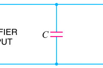
*Hook up a multimeter in series with the signal to the DCS to measure current signal.
*Apply water level until 0% marking on chamber
*Multimeter should show 4mA
If not, do zero adjustment at transmitter using HART Communicator
Apply water level until 100% marking on chamber
*Multimeter should show 20mA
*If not, do span adjustment at transmitter using HART Communicator
*Verify the linearity by increasing and decreasing the pressure (0%,25%,50%,75%,100%,75%,50%,25% and 0%of range)
*After completion of the job ask panel operator to put loops back in normal mode or normalize the MOS

Example Calculation:

Low S.G=0.802
High S.G= 0.992
A= 810mm (measurement length)

At 0% Level = (A x Low S.G)
= (810 x 0.802)
= 649.42 mm

At 100% Level = (A x High S.G)
= (810 x 0.992)
= 803.52 mm

Also Read: Displacer Level Transmitter Working Principle

Don't Miss Our Updates
Be the first to get exclusive content straight to your email.
We promise not to spam you. You can unsubscribe at any time.
Invalid email address
You've successfully subscribed !

Continue Reading

Potentiometric Level Measurement Principle
Electrical Standards
Hierarchy of Calibration Organizations
Displacer Level Transmitter 5-point Calibration
Servo Level Transmitter Principle
Magnetic Level Indicator Principle, Limitations, Installation and Calibration
Share This Article
Facebook Whatsapp Whatsapp LinkedIn Copy Link
Share
14 Comments
  • K sreenivasan says:
    March 28, 2017 at 1:59 pm

    Excellent article
    I would suggest that the following line can be added in the beginning.
    Obtain suitable permit to work (PTW)from operation group

    Reply
  • jairo francisco says:
    October 6, 2017 at 11:20 pm

    I have doubts about What does MOS mean?

    What is SG?

    Reply
    • Nuar says:
      October 7, 2017 at 11:38 pm

      MOS : maintenance override system
      SG: specific gravity

      Reply
      • pirle says:
        October 26, 2017 at 2:31 pm

        is SG variable and how to calculate it ? thanks

        Reply
  • Varma says:
    October 26, 2017 at 3:11 pm

    Sg is specific gravity. Every liquid have a specific Sg value. you can check their datasheets or properties. If you don’t have those values then ask process engineers, they will give the readings. No need to calculate the Sg.

    Reply
    • tanmay kumar behera says:
      May 15, 2018 at 12:41 pm

      What is low s.g and high s.g please clear?

      Reply
      • azetou says:
        May 16, 2018 at 1:55 pm

        Hi,
        if there is two fluids in the vessel then the high SG will be of the fluid at the bottom and the low SG will be of the fluid above it, an example is water and oil, water will be at the bottom because it is heavier (SG = 1) and the oil will be at the top because it is lighter (SG around 0.8)
        Regards.

        Reply
      • BHARAT KUMAR says:
        May 16, 2018 at 7:46 pm

        Specific is the density w.r.t to water, Higher the s.g the more the mass or the pressure that is exerted downward will be more…P=(s.g) .g.H

        Reply
  • Darwin says:
    August 6, 2019 at 3:58 pm

    hi! i have encountered issue with interface level. we check dry calibration using correct mass 5 point che no issue found.

    However when we connect to the vessel it will show not correct level. The problem of transmitter is lower reading compare to sight glass.

    For example tx 33% but level magnetic sight glass shown 55%.

    I tried also wet calibration as u mention above using ur formula transmitter reading is correct.

    do you have any suggestion how to solve this problem ?

    Reply
  • Nabil Hassan says:
    August 6, 2019 at 9:32 pm

    It’s very important website for Supplemental information to
    making a complete image about this science field .

    Reply
  • Brian Seeton says:
    November 29, 2020 at 9:20 pm

    This is the reason interface levels and displacers in general are mis calibrated. Your dwg repesents a zero on the sight glass the displacer cant even measure as it it shown. Anyone thats done a few of these knows the displacer/float tube cant go beyond the bottom of the cage…..
    Horrible example!!!!
    And thus why levels are almost always the most incorrectly calibrated devices in the field due to bad information being passed to tech’s!

    Reply
  • farhan says:
    December 5, 2020 at 9:39 am

    i have one question
    we have here interface level transmitter displacer type , in service there is two liquid crude oil and water.
    how we will calibrate this level transmitter with water only.
    could you please send me the calculation

    Reply
  • farhan says:
    December 5, 2020 at 11:47 am

    could any one can explain the calibration of interface level transmitter with water only,
    service is crude oil and water and we have to calibrate by water only
    please share with me calculation.

    Reply
  • Avaz Abdullayev says:
    September 3, 2024 at 3:14 pm

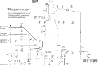
    Therefore we, have to perform single point verification of all level indicators including sight glass, nucleonic, radar an displacer as per sketch dwg at their 50% indication or reading.

    Reply

Leave a Reply Cancel reply

Your email address will not be published. Required fields are marked *

Stay Connected

128.3kFollowersLike
69.1kFollowersFollow
208kSubscribersSubscribe
38kFollowersFollow

Categories

Explore More

Siemens Differential Pressure Transmitter Calculations (Flange Type)
Probe Type GWR Level Transmitter Working Animation
Overview of Tank Gauging Technologies
The Principle of Dead Weight Pressure Tester
What is a Submersible Pressure Transmitter? Principle, Advantages
How a Level Switch Works
Guided-Wave Radar Instruments Diagnostics
Installation and Calibration of Level Transmitter

Keep Learning

Instrument Linearity Error

Instrument Errors – Zero, Span, Linearity

process chemical analyzer calibration

Automated Calibration

Wet Leg Level Transmitter

Basics of DP Level Measurement

Multimeter Digits

Multimeter – What Do Digits and Counts Mean?

Alternative Vessel Level Indication

What is the Simple Alternative Vessel Level Indication?

Bubbler Liquid Level Transmitter Calculation

Bubbler Liquid Level Transmitter Calculation

Closed Tank Application

Zero Elevation and Zero Suppression in Level Measurement

Radiation Level Measurement Principle

Radiation Level Measurement

Learn More

DP Transmitter Level Measurement for Closed Tank Wet leg Method

DP Transmitter Dry Leg & Wet Leg Calculations

Reformer Tube Stress Relief Reusable Furnace

Miscellaneous Electrical Tasks – Repaired Reformer Tubes Weld Stress Relief

Electrical Machines Questions and Answers

Synchronous Machines EMF Polygon Questions

AC Generator Nameplate Ratings

AC Generator Nameplate Ratings

CRA Module in Schneider PLC

CRA Module in Schneider PLC – Remote IO Adapter Module

Safety interlock for motor starters in Siemens PLC

Motor Starter Logic using Siemens PLC Tia Portal

Two Differential Pressure Transmitters

Pressure Level Transmitter Problems

Target Flow Transmitter Problem

Unreliable Ammonia Flow Transmitter Reading and Problems

Follow US
All rights reserved. Reproduction in whole or in part without written permission is prohibited.
Welcome Back!

Sign in to your account

Username or Email Address
Password

Lost your password?