Basics of Ladder Diagram in PLC Programming
Learn PLC Programming : Watch Video
Ladder logic was originally a written method to document the design and construction of relay racks as used in manufacturing and process control.Each device in the relay rack would be represented by a symbol on the ladder diagram with connections between those devices shown. In addition, other items external to the relay rack such as pumps, heaters, and so forth would also be shown on the ladder diagram.
Ladder logic has evolved into a programming language that represents a program by a graphical diagram based on the circuit diagrams of relay logic hardware. Ladder logic is used to develop software for programmable logic controllers (PLCs) used in industrial control applications. The name is based on the observation that programs in this language resemble ladders, with two vertical rails and a series of horizontal rungs between them. While ladder diagrams were once the only available notation for recording programmable controller programs, today other forms are standardized in IEC 61131-3.
Ladder logic is widely used to program PLCs, where sequential control of a process or manufacturing operation is required. Ladder logic is useful for simple but critical control systems. As programmable logic controllers became more sophisticated it has also been used in very complex automation systems. Often the ladder logic program is used in conjunction with an HMI program operating on a computer workstation.
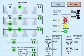
Example of a simple ladder logic program
The language itself can be seen as a set of connections between logical checkers (contacts) and actuators (coils). If a path can be traced between the left side of the rung and the output, through asserted (true or “closed”) contacts, the rung is true and the output coil storage bit is asserted or true. If no path can be traced, then the output is false (0) and the “coil” by analogy to electromechanical relays is considered “de-energized”.
Ladder logic has contacts that make or break circuits to control coils. Each coil or contact corresponds to the status of a single bit in the programmable controller’s memory. Unlike electromechanical relays, a ladder program can refer any number of times to the status of a single bit, equivalent to a relay with an indefinitely large number of contacts.
So-called “contacts” may refer to physical (“hard”) inputs to the programmable controller from physical devices such as pushbuttons and limit switches via an integrated or external input module, or may represent the status of internal storage bits which may be generated elsewhere in the program.
Each rung of ladder language typically has one coil at the far right. Some manufacturers may allow more than one output coil on a rung.
- —( )— A regular coil, energized whenever its rung is closed.
- —()— A “not” coil, energized whenever its rung is open.
- —[ ]— A regular contact, closed whenever its corresponding coil or an input which controls it is energized.
- —[]— A “not” contact, closed whenever its corresponding coil or an input which controls it is not energized.
The “coil” (output of a rung) may represent a physical output which operates some device connected to the programmable controller, or may represent an internal storage bit for use elsewhere in the program.
Logical AND
------[ ]--------------[ ]----------------( ) Key Switch 1 Key Switch 2 Door Motor |
The above realizes the function: Door Motor = Key Switch 1 AND Key Switch 2
This circuit shows two key switches that security guards might use to activate an electric motor on a bank vault door. When the normally open contacts of both switches close, electricity is able to flow to the motor which opens the door.
Logical AND with NOT
------[ ]--------------[]----------------( ) Close Door Obstruction Door Motor |
The above realizes the function: Door Motor = Close door AND NOT(Obstruction).
This circuit shows a pushbutton that closes a door, and an obstruction detector that senses if something is in the way of the closing door. When the normally open push button contact closes and the normally closed obstruction detector is closed (no obstruction detected), electricity is able to flow to the motor which closes the door.
Logical OR
 --+-------[ ]-------+-----------------( )
   | Exterior Unlock |                 Unlock
   |                 |
   +-------[ ]-------+
     Interior Unlock
|
The above realizes the function: Unlock = Interior Unlock OR Exterior Unlock
This circuit shows the two things that can trigger a car’s power door locks. The remote receiver is always powered. The lock solenoid gets power when either set of contacts is closed.
Industrial STOP/START
In common industrial latching start/stop logic we have a “start” button to turn on a motor contactor, and a “stop” button to turn off the contactor.
When the “start” button is pushed the input goes true, via the “stop” button NC contact. When the “run” input becomes true the seal-in “run” NO contact in parallel with the “start” NO contact will close maintaining the input logic true (latched or sealed-in). After the circuit is latched the “stop” button may be pushed causing its NC contact to open and consequently the input to go false. The “run” NO contact then opens and the circuit logic returns to its quiescent state.
 --+----[ ]--+----[]----( )
   |   start |   stop    run
   |         |
   +----[ ]--+
        run
 -------[ ]--------------( )
        run             motor
|
The above realizes the function: run = ( start OR run ) AND ( NOT stop )
Note the use of parenthesis to group the logical OR function before evaluating the logical AND function (which has a higher order of operation priority). Also note the use of NOT to represent the “stop” NC contact logic.
This latch configuration is a common idiom in ladder logic. In ladder logic it is referred to as seal-in logic. The key to understanding the latch is in recognizing that “start” switch is a momentary switch (once the user releases the button, the switch is open again). As soon as the “run” solenoid engages, it closes the “run” NO contact, which latches the solenoid on. The “start” switch opening up then has no effect.
For safety reasons, an Emergency-Stop and/or Stop should be hardwired in series with the Start switch, and the relay logic should reflect this.
 --[]----[]----+--[ ]--+---------( )
   ES    Stop    | Start |        Motor
                 |       |
                 +--[ ]--+
                    Run
|
Complex logic
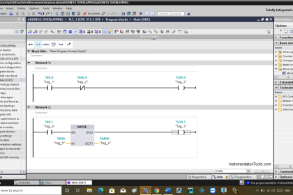
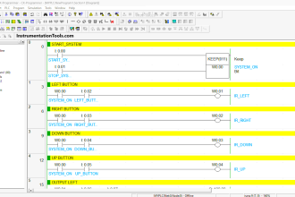
Here is an example of what two rungs in a ladder logic program might look like. In real world applications, there may be hundreds or thousands of rungs.
Typically, complex ladder logic is ‘read’ left to right and top to bottom. As each of the lines (or rungs) are evaluated the output coil of a rung may feed into the next stage of the ladder as an input. In a complex system there will be many “rungs” on a ladder, which are numbered in order of evaluation.
 1. ----[ ]---------+----[ ]-----+----( )
      Switch        |   HiTemp   |    A/C
                    |            |
                    +----[ ]-----+
                        Humid
 2. ----[ ]----[]--------------------( )
        A/C    Heat                 Cooling
|
Line 1 realizes the function: A/C = Switch AND ( HiTemp OR Humid )
Line 2 realizes the function: Cooling = A/C AND ( NOT Heat )
This represents a slightly more complex system for rung 2. After the first line has been evaluated, the output coil “A/C” is fed into rung 2, which is then evaluated and the output coil “Cooling” could be fed into an output device “Compressor” or into rung 3 on the ladder. This system allows very complex logic designs to be broken down and evaluated.
Additional functionality
Additional functionality can be added to a ladder logic implementation by the PLC manufacturer as a special block. When the special block is powered, it executes code on predetermined arguments. These arguments may be displayed within the special block.
                              +-------+
  -----[ ]--------------------+  A    +----
   Remote Unlock              +-------+
                           Remote Counter
                              +-------+
  -----[ ]--------------------+  B    +----
   Interior Unlock            +-------+
                          Interior Counter
                      +--------+
  --------------------+ A + B  +-----------
                      | into C |
                      +--------+
                         Adder
|
In this example, the system will count the number of times that the interior and remote unlock buttons are pressed. This information will be stored in memory locations A and B. Memory location C will hold the total number of times that the door has been unlocked electronically.
PLCs have many types of special blocks. They include timers, arithmetic operators and comparisons, table lookups, text processing, PID control, and filtering functions. More powerful PLCs can operate on a group of internal memory locations and execute an operation on a range of addresses, for example, to simulate a physical sequential drum controller or a finite state machine. In some cases, users can define their own special blocks, which effectively are subroutines or macros. The large library of special blocks along with high speed execution has allowed use of PLCs to implement very complex automation systems.


This is a very good information, thanks for share them, go ahead.