Inst ToolsInst ToolsInst Tools
  • Ask
  • Courses
  • Videos
  • Q & A
    • Interview
      • Instrumentation
      • Electronics
      • Electrical
      • Practical Questions
    • MCQ
      • Instrumentation MCQ
      • Electrical MCQ
      • Electronics MCQ
      • Control Systems MCQ
      • Analog Electronics MCQ
      • Digital Electronics MCQ
      • Power Electronics MCQ
      • Microprocessor MCQ
      • Multiple Choice Questions
  • EE
    • Electronics
      • Electronics Q & A
      • Electronic Basics
      • Electronic Devices & Circuits
      • Electronics Animation
      • Digital Electronics
    • Electrical
      • Electrical Basics
      • Electrical Q & A
      • Power Electronics
      • Electrical Machines
      • Electrical Animation
      • Power Systems
      • Switchgear & Protection
      • Transmission & Distribution
  • Measure
    • Control Valves
    • Calibration
    • Temperature
    • Pressure
    • Flow
    • Level
    • Analyzers
    • Switches
    • Vibration
    • Solenoid Valve
  • Control
    • PLC Tutorials
    • Control Systems
    • Safety Instrumented System (SIS)
    • Communication
    • Fire & Gas System
  • More
    • Design
    • Tools
    • Animation
    • Basics
    • Formulas
    • Standards
    • TextBooks
    • Common
    • Software
    • Excel Tools
    • Erection & Commissioning
    • Process Fundamentals
    • Videos
    • Books
Search
All rights reserved. Reproduction in whole or in part without written permission is prohibited.
Reading: Ohm Meter
Share
Notification Show More
Font ResizerAa
Inst ToolsInst Tools
Font ResizerAa
  • Courses
  • PLC Tutorials
  • Control Systems
Search
  • Ask
  • Courses
  • Videos
  • Q & A
    • Interview
    • MCQ
  • EE
    • Electronics
    • Electrical
  • Measure
    • Control Valves
    • Calibration
    • Temperature
    • Pressure
    • Flow
    • Level
    • Analyzers
    • Switches
    • Vibration
    • Solenoid Valve
  • Control
    • PLC Tutorials
    • Control Systems
    • Safety Instrumented System (SIS)
    • Communication
    • Fire & Gas System
  • More
    • Design
    • Tools
    • Animation
    • Basics
    • Formulas
    • Standards
    • TextBooks
    • Common
    • Software
    • Excel Tools
    • Erection & Commissioning
    • Process Fundamentals
    • Videos
    • Books
Follow US
All rights reserved. Reproduction in whole or in part without written permission is prohibited.
Inst Tools > Blog > Electrical Theory > Ohm Meter

Ohm Meter

Last updated: August 8, 2018 4:08 pm
Editorial Staff
Electrical Theory
No Comments
Share
5 Min Read
SHARE

The ohm meter is an instrument used to determine resistance. A simple ohm meter (Below Figure) consists of a battery, a meter movement calibrated in ohms, and a variable resistor.

Ohm Meter Circuit

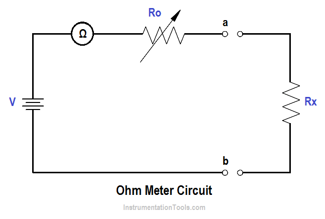
Ohm meters are connected to a component which is removed from the circuit as illustrated in Figure. The reason for removing the component is that measurement of current through the component determines the resistance. If the component remains in the circuit, and a parallel path exists in the circuit, the current will flow in the path of least resistance and give an erroneous reading.

Ro in above Figure, is an adjustable resistor whose purpose is to zero the ohm meter and correct for battery aging. It is also a current-limiting resistor which includes the meter resistance Rm. Zeroing the ohm meter is accomplished by shorting the ohm meter terminals ab and adjusting Ro to give full-scale deflection.

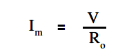
The below Equation is the mathematical representation for determining full-scale deflection meter current.

full-scale deflection meter

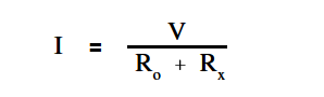
When the unknown resistance Rx is connected across the ohm meter terminals, the current is measured by calculating the total series resistance and applying above Equation.

The below Equation is the mathematical representation of this concept.

Ohm Meter Circuit Formula

An easy way to determine ohm meter deflection is by use of a deflection factor (D). Deflection factor is the ratio of circuit current to meter current.

The below Equation is the mathematical representation of the deflection factor.Ohm Meter Deflection Factor

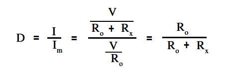
The current through the circuit can be determined by solving for I.

The below Equation is the mathematical representation of this relationship.

I = D Im

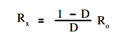
To solve for Rx , using above Equation and ” Im” equation, the relationship between deflection factor and the meter resistance to the unknown resistance can be shown. The below Equation is the mathematical representation of this relationship.

Ohm Meter Circuit Formula - 1

If half-scale deflection occurs, then R = Ro , so that the value of Rm is marked at mid-scale on the ohm meter face.

Example 1:

An ohm meter has a meter movement with a 100 µA full-scale deflection. The open circuit voltage at terminals ab is 24 V. The ohm meter is zeroed and then an unknown resistance Rx is measured, which produces quarter-scale deflection. Find Rx

Solution:

First find Ro

Ro = V/Im

Ro = 24/(1 x 10-6)

Ro = 240 KΩ

Then solve for Rx :

Ohm Meter Circuit Formula - 1

Rx = { ( 1 – 1/4) / (1/4) } 240

Rx = 720 KΩ

Therefore, quarter scale deflection of this ohm meter face would read 720 KΩ.

Example 2:

An ohm meter with Ro =30Ω, and full scale current Im = 300 µA.

Find I with: 1) 0 Ω, 2) 5Ω, 3) 10Ω, 4) 15Ω, and 5) 1 MΩ resistors across the meter terminal.

Solution:

First, the deflection factor for each resistor must be found.

D =  Ro / ( Ro +  Rx )

For Rx  = 0 Ω

D = 30/30 = 1

For Rx  = 5 Ω

D = 30/(30+5) = 0.86

For Rx  = 10 Ω

D = 30/(30+10) = 0.75

For Rx  = 15 Ω

D = 30/(30+15) = 0.67

For Rx  = 1 M Ω

D = 30/(30+5M) = 1 x 10⁻⁶

Then find I by using:

I = D Im

For Rx  = 0 Ω

I = 1  ( 300 x 10-6 ) = 300 μA (full scale deflection)

For Rx  = 5 Ω

I = 0.86  ( 300 x 10-6 ) = 258 μA

For Rx  = 10 Ω

I = 0.75  ( 300 x 10-6 ) = 225 μA

For Rx  = 15 Ω

I = 0.67  ( 300 x 10-6 ) = 201 μA

For Rx  = 1 M Ω

I = 0  ( 300 x 10-6 ) = 0 μA  (zero deflection)

NOTE: As the resistance was increased from 0 to 5Ω, meter current decreased by 42 µA. Similarly, when resistance was increased from 5 to 10Ω, the current decreased by 33 µA. Thus, an ammeter scale used to measure resistance is nonlinear (below Figure).

Ohm Meter Scale

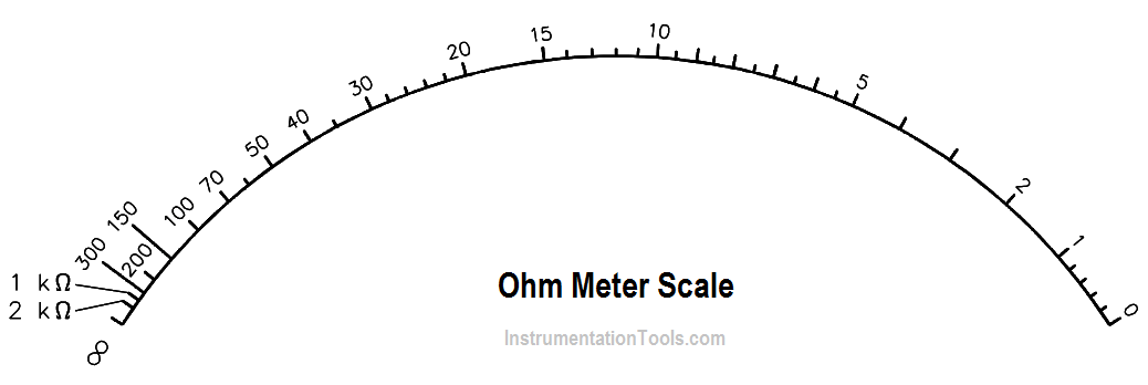
The ohm meter scale is a reversal of the ammeter and voltmeter scales. In other words, the zero resistance (Rx = 0) is at the right end of the scale and infinite resistance (Rx = 1MΩ) is at the left end of the scale.

Don't Miss Our Updates
Be the first to get exclusive content straight to your email.
We promise not to spam you. You can unsubscribe at any time.
Invalid email address
You've successfully subscribed !
Moving Iron Vane Meter Movement
Calculate Power in Series RC Circuit
Discharge and Charging of Lead-Acid Battery
Capacitance
Thermocouples
Share This Article
Facebook Whatsapp Whatsapp LinkedIn Copy Link
Share
Leave a Comment

Leave a Reply Cancel reply

Your email address will not be published. Required fields are marked *

Stay Connected

128.3kFollowersLike
69.1kFollowersFollow
208kSubscribersSubscribe
38kFollowersFollow

Categories

Recent Comments

  • Kamli on Top Free PLC Software
  • Guifty Shimica on Top Non-PLC Certification Courses for Automation Professionals
  • Guifty Shimica on Top Non-PLC Certification Courses for Automation Professionals
  • MIHARITSOA Aina Sitraka on Top Non-PLC Certification Courses for Automation Professionals

Related Articles

Core-Type Transformer

Transformer Turns Ratio

Three Phase Transformer Connections

Three Phase Transformer Connections

Parallel Circuit Unknown Resistance

Simplified Formulas for Parallel Circuit Resistance Calculations

Parallel Open Circuit Fault

Parallel Open Circuit Faults

Phase angle

AC Generation Analysis : Effective Values, Phase Angle and Frequency

Core-Type Transformer

Transformer Theory of Operation

AC Generator Nameplate Ratings

AC Generator Nameplate Ratings

Shunt-Wound DC Generator Principle

Shunt-Wound DC Generators

More Articles

What is a Fieldbus?

ball Valve Animation

Basics of Ball Valves

Junction Box Cooler

Junction Box Internal Corrosion Problems and Solutions

What is electrical transformer

Transformer Impedance Ratio

Globe Control Valve Animation

Basics of Globe Valves

PLC Structured Text Program for Light Sequences via Timers

PLC Structured Text Program for Light Sequences via Timers

Open Systems Interconnection

What is Open Systems Interconnection?

AC Induction Motor Construction

Basics of AC Induction Motors

Follow US
All rights reserved. Reproduction in whole or in part without written permission is prohibited.
Welcome Back!

Sign in to your account

Username or Email Address
Password

Lost your password?