Inst ToolsInst ToolsInst Tools
  • Courses
  • Automation
    • PLC
    • Control System
    • Safety System
    • Communication
    • Fire & Gas System
  • Instrumentation
    • Design
    • Pressure
    • Temperature
    • Flow
    • Level
    • Vibration
    • Analyzer
    • Control Valve
    • Switch
    • Calibration
    • Erection & Commissioning
  • Interview
    • Instrumentation
    • Electrical
    • Electronics
    • Practical
  • Q&A
    • Instrumentation
    • Control System
    • Electrical
    • Electronics
    • Analog Electronics
    • Digital Electronics
    • Power Electronics
    • Microprocessor
  • Request
Search
  • Books
  • Software
  • Projects
  • Process
  • Tools
  • Basics
  • Formula
  • Power Plant
  • Root Cause Analysis
  • Electrical Basics
  • Animation
  • Standards
  • 4-20 mA Course
  • Siemens PLC Course
Reading: PLC Program for Control Valve Scaling
Share
Font ResizerAa
Inst ToolsInst Tools
Font ResizerAa
  • Courses
  • Design
  • PLC
  • Interview
  • Control System
Search
  • Courses
  • Automation
    • PLC
    • Control System
    • Safety System
    • Communication
    • Fire & Gas System
  • Instrumentation
    • Design
    • Pressure
    • Temperature
    • Flow
    • Level
    • Vibration
    • Analyzer
    • Control Valve
    • Switch
    • Calibration
    • Erection & Commissioning
  • Interview
    • Instrumentation
    • Electrical
    • Electronics
    • Practical
  • Q&A
    • Instrumentation
    • Control System
    • Electrical
    • Electronics
    • Analog Electronics
    • Digital Electronics
    • Power Electronics
    • Microprocessor
  • Request
Follow US
All rights reserved. Reproduction in whole or in part without written permission is prohibited.
Inst Tools > Blog > PLC Tutorials > PLC Program for Control Valve Scaling

PLC Program for Control Valve Scaling

PLC Analog Scaling example for the valve. We discuss about PLC Program for Control Valve Scaling using Siemens PLC Programming software.

Last updated: November 3, 2023 11:46 am
Editorial Staff
PLC Tutorials
4 Comments
Share
5 Min Read
SHARE

This is a PLC Program to implement analog scaling in S7-300 PLC.

Contents
Control Valve ScalingProblem DiagramProblem SolutionList of inputs/outputsPLC Ladder Diagram for Valve ScalingLadder Logic ExplainedResult

Control Valve Scaling

Problem Description

Implement PLC program in S7-300 for analog scaling.

Problem Diagram
PLC Program for Control Valve Scaling

Problem Solution

Analog inputs come from different sensors or transmitters. Transmitters convert physical quantity into electrical signal. We can measure many physical quantity by using analog sensors such as temperature, pressure, level, distance, flow etc.

Of course we can measure all physical quantity by using analog sensors, but for example and explanation purpose here we take one example of control valve.

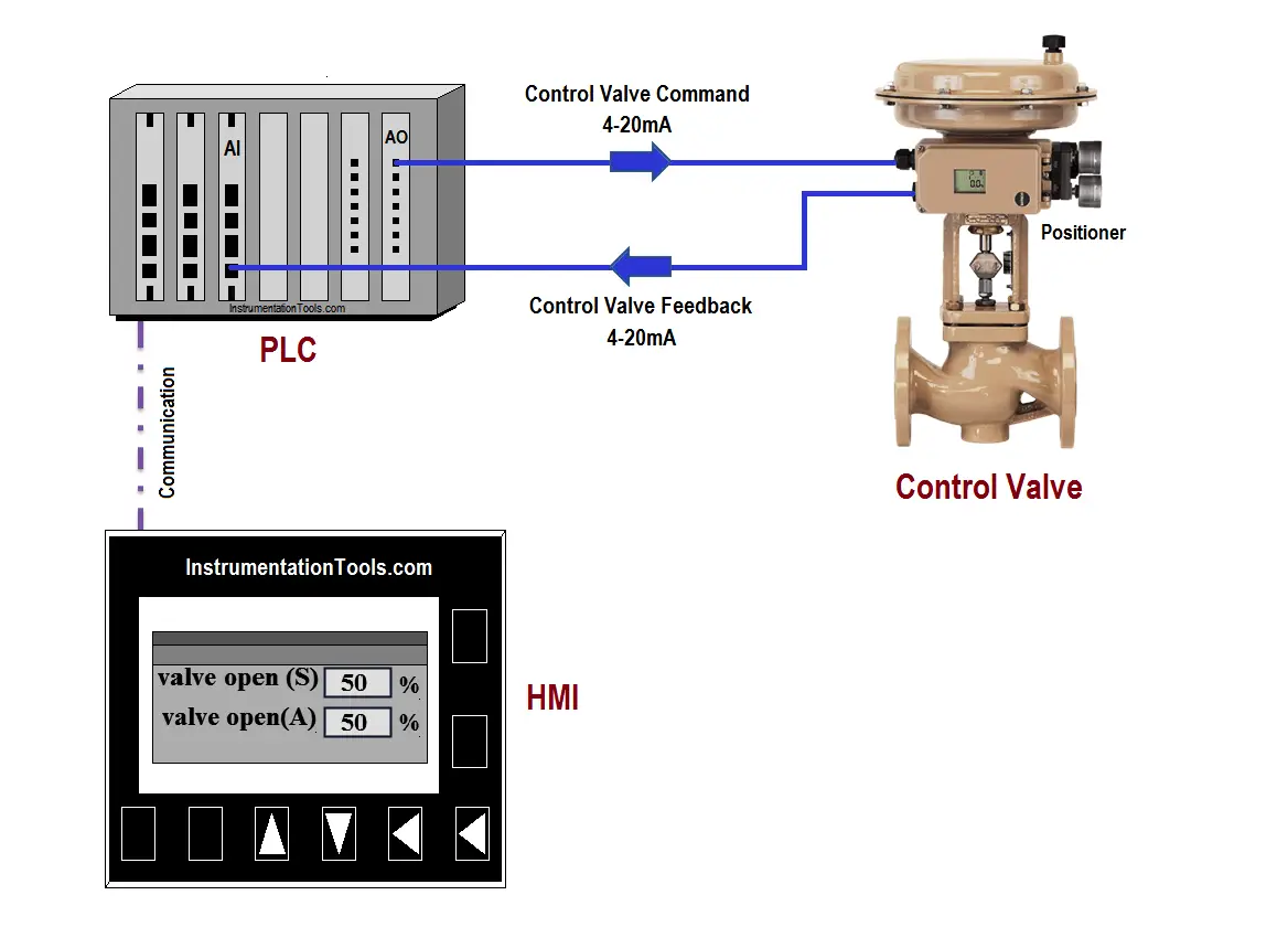
As shown in figure, here we consider one control valve and it has 4-20mA output (valve feedback)  and 4-20mA input (valve command) for operation. Hence, when PLC will give 20mA to flow control valve, valve will be open 100% and for 4mA it will be 0% (close).

In other way flow control valve is also providing output signal that can be used for close loop system/for valve percentage indication. If valve is 100% open, PLC will get 20mA signal and for 0% it will get 4mA.

Note:- We consider here close loop system for simple explanation, so operator will set control valve open command parameter in range between 0% to 100% .

PLC Valve Open Command

Now as per close loop system, control valve will provide output signal (valve feedback) and by using SCALE instruction, operator can see actual valve open parameter on graphics.

PLC Valve Feedback value

List of inputs/outputs

M memory

  • Enable command-Scaling :- M0.0
  • Bipolar selection-Scaling :- M0.1
  • Actual value from the sensor or transmitter :- MW10
  • Error word –Scaling :- MW12
  • Scaled output :- MD20
  • Enable command-Unscaling :- M1.0
  • Bipolar selection- Unscaling :- M0.2
  • Given value from the display :- MD24
  • Error word-Unscaling :- MW16
  • Unscaled output :- MW26

PLC Ladder Diagram for Valve Scaling

PLC Control Valve Scaling

Valve PLC Scale

Ladder Logic Explained

For this application, we use S7-300 PLC and TIA portal software for programming. We can implement this logic by using other PLC also.

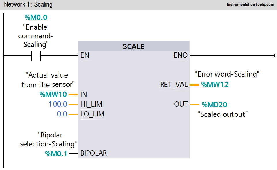
Network 1:

In this network, scaling logic is executed when Enable command (M0.0) is ON.

The “Scale” instruction is to convert the integer (here 4-20mA signal from the control valve or MW10) at the IN parameter which can be scaled in physical units between a low limit (0% output) and a high limit (100% output).

The result or scaled output (MD20) of the instruction is output at the OUT parameter.

If bipolar selection (M0.1) is ON, it is assumed that the value at the IN parameter is bipolar (range between -27648 to +27648).

If bipolar selection (M0.1) is OFF, it is assumed that the value at the IN parameter is unipolar (range between 0 to 27648).

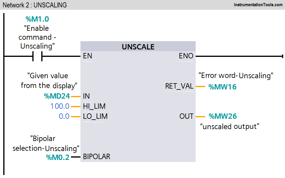
Network 2:

The “Unscale” instruction is used to unscaled the floating-point number (given value from the display or MD24) on the IN parameter into physical units between a low limit and and a high limit.

The result of the instruction is output (unscaled output MW26) at the OUT parameter. If bipolar selection (M0.2) is ON, it is assumed that the value at the IN parameter is bipolar (range between -27648 to +27648).

If bipolar selection (M0.2) is OFF, it is assumed that the value at the IN parameter is unipolar (range between 0 to 27648).

Error code table:

PLC analog block error codes

Note: The above application may be different from actual application. This example is only for explanation purpose only. We can implement this logic in other PLC also. This is the simple concept of SCALE and UNSCALE instructions, we can use this concept in other examples also.

All parameters considered in the example are for explanation purposes only, parameters may be different in actual applications.

Result

Simulation for analog scaling in S7-300 PLC

Author : Bhavesh

If you liked this article, then please subscribe to our YouTube Channel for PLC and SCADA video tutorials.

You can also follow us on Facebook and Twitter to receive daily updates.

Read Next:

  • Sensor Scaling in PLC
  • Latching Function in PLC
  • PLC Ladder Diagrams
  • Multiple Outputs using PLC
  • PLC Continuous Filling Operation
Don't Miss Our Updates
Be the first to get exclusive content straight to your email.
We promise not to spam you. You can unsubscribe at any time.
Invalid email address
You've successfully subscribed !

Continue Reading

PLC Timer Programming Examples – TON, TOF, TP and TONR
How to use Sub Routines with Allen Bradley PLC
PLC Program to Heat and Bend Glass Tubes
How to Select a SCADA for New PLC Project?
PLC Ladder Logic for Start-up Control of Boilers
PLC Programming for Garden Sprinkler System
Share This Article
Facebook Whatsapp Whatsapp LinkedIn Copy Link
Share
4 Comments
  • adams says:
    August 2, 2018 at 8:24 pm

    how about a similar article like this using the SCP instruction of Allen Bradley thanks nice work here

    Reply
    • Nick Camplin says:
      February 6, 2022 at 6:27 pm

      It is important to explain where you get the range values of +27648 to -27648.

      Reply
  • Qadir Mohtasham says:
    August 3, 2018 at 10:04 am

    Great

    Reply
  • satish says:
    October 11, 2018 at 11:44 am

    Please upload types and makes PLC with photos, IO card to different types of field instruments and identification of errors in PLC

    Reply

Leave a Reply Cancel reply

Your email address will not be published. Required fields are marked *

Stay Connected

128.3kFollowersLike
69.1kFollowersFollow
210kSubscribersSubscribe
38kFollowersFollow

Categories

Explore More

Global Acknowledgment Instruction in Safety PLC
Finding the Best PLC for Your Project – Tips and Tricks
Timers in PLC Programming – Siemens Tia Portal Tutorials
Troubleshooting a 4-20mA Current loop
Functions of SCADA
System Cabinet Health Checks – PLC and DCS Industrial Automation
PLC Fault Diagnosis – PLC Training Documents
Why different PLC Programming Languages were Developed?

Keep Learning

Program to implement T Flip Flop logic

T Flip Flop PLC Ladder Diagram

Delta PLC Simulator

How to Work with Delta PLC Simulator?

PLC Automation for Product Weighing and Labeling

PLC Controlled Conveyor and Weighing with Labeling Automation

Omron PLC Online Training Course

Omron PLC Online Training Course

Omron PLC Example

Design a Water Pump PLC Program using CX-Programmer

Online time of the PLC

System and Local Time in PLC

Fixed PLC

#19 PLC Best Practices – Monitor PLC Memory Usage

LIFO Instruction in Allen Bradley PLC Programming

LIFO Instruction in PLC

Learn More

Falling Positive and Falling Negative Instructions in PLC

Positive and Negative Edges using Statement List Language

System Architecture in Industrial Automation

How to Design a System Architecture in Industrial Automation?

oxygen Safety Analyzer

Oxygen Safety Analyzer

Electrical Conductivity Meter

What is the Application of Electrical Conductivity Meter?

Comparison of Accuracy and Precision

Difference between Accuracy and Precision

Difference Between Squirrel Cage and Slip Ring Motors

Electrical Circuit Breaker Quiz

100 Electrical Circuit Breaker Quiz

Shielded Cables

The Idea Behind Shielded Cables

Menu

  • About
  • Privacy Policy
  • Copyright

Quick Links

  • Learn PLC
  • Helping Hand
  • Part Time Job

YouTube Subscribe

Follow US
All rights reserved. Reproduction in whole or in part without written permission is prohibited.
Welcome Back!

Sign in to your account

Username or Email Address
Password

Lost your password?