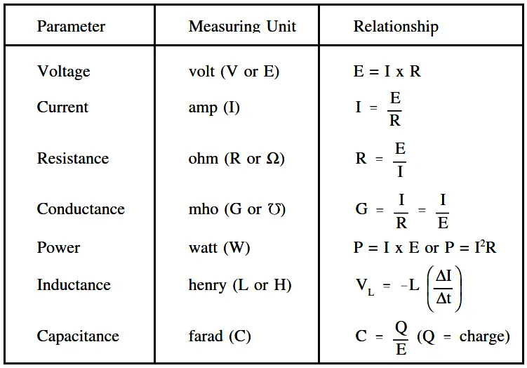
Using Ohm’s Law and the System Internationale (SI) Metric System, electrical measuring units can be derived.
The following electrical parameters, including the unit of measurement and the relationship to other parameters.
- Voltage
- Current
- Resistance
- Conductance
- Power
- Inductance
- Capacitance
System Internationale (SI) Metric System
Electrical units of measurement are based on the International (metric) System, also known as the SI System. Units of electrical measurement include the following:
- Ampere
- Volt
- Ohm
- Siemens
- Watt
- Henry
- Farad etc.
Voltage
Voltage, electromotive force (emf), or potential difference, is described as the pressure or force that causes electrons to move in a conductor. In electrical formulas and equations, you will see voltage symbolized with a capital E, while on laboratory equipment or schematic diagrams, the voltage is often represented with a capital V.
Current
Electron current, or amperage, is described as the movement of free electrons through a conductor. In electrical formulas, current is symbolized with a capital I, while in the laboratory or on schematic diagrams, it is common to use a capital A to indicate amps or amperage (amps).
Resistance
Now that we have discussed the concepts of voltage and current, we are ready to discuss a third key concept called resistance. Resistance is defined as the opposition to current flow. The amount of opposition to current flow produced by a material depends upon the amount of available free electrons it contains and the types of obstacles the electrons encounter as they attempt to move through the material.
Resistance is measured in ohms and is represented by the symbol (R) in equations. One ohm is defined as that amount of resistance that will limit the current in a conductor to one ampere when the potential difference (voltage) applied to the conductor is one volt. The shorthand notation for ohm is the Greek letter capital omega (Ω). If a voltage is applied to a conductor, current flows. The amount of current flow depends upon the resistance of the conductor. The lower the resistance, the higher the current flow for a given amount of voltage. The higher the resistance, the lower the current flow.
Ohm’s Law
In 1827, George Simon Ohm discovered that there was a definite relationship between voltage, current, and resistance in an electrical circuit.
Ohm’s Law defines this relationship and can be stated in three ways.
1. Applied voltage equals circuit current times the circuit resistance.
The below Equation is a mathematical representation of this concept.
E=IxR or E=IR
2. Current is equal to the applied voltage divided by the circuit resistance.
The below Equation is a mathematical representation of this concept.
I = E / R
3. Resistance of a circuit is equal to the applied voltage divided by the circuit current.
The below Equation is a mathematical representation of this concept.
R (orΩ) = E / I
where
I = current (A), E = voltage (V), R = resistance (Ω)
If any two of the component values are known, the third can be calculated.
Example 1:
Given that I=2 A, E=12 V,find the circuit resistance.
Solution:
Since applied voltage and circuit current are known, use Ohm’s Law to solve for resistance.
R = E / I
R = 12 V / 2 A = 6 Ω
Example 2:
Given E=260 V and R=240 Ω, what current will flow through a circuit?
Solution:
Since applied voltage and resistance are known, use Ohm’s Law to solve for current.
I = E / R
I = 260 V / 240 Ω = 1.083 A
Example 3:
Find the applied voltage, when given circuit resistance of 100 Ω and circuit current of 0.5 amps.
Solution:
Since circuit resistance and circuit current are known, use Ohm’s Law to solve for applied voltage.
E=IR
E = (0.5 A)(100 Ω)= 50 V
Conductance
The word “reciprocal” is sometimes used to mean “the opposite of.” The opposite, or reciprocal, of resistance is called conductance. As described above, resistance is the opposition to current flow. Since resistance and conductance are opposites, conductance can be defined as the ability to conduct current.
For example, if a wire has a high conductance, it will have low resistance, and vice-versa. Conductance is found by taking the reciprocal of the resistance. The unit used to specify conductance is called “mho,” which is ohm spelled backwards. The symbol for “mho” is the Greek letter omega inverted (℧ ).
The symbol for conductance when used in a formula is G.
The below Equation is the mathematical representation of conductance obtained by relating the definition of conductance (1/R) to Ohm’s Law Equation.
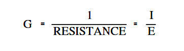
Example:
If a resistor (R) has five ohms, what will its conductance (G) be in mhos ?
Solution:
G (or ℧ ) = 1 / R = 1 / 5 = 0.2 ℧
Power
Electricity is generally used to do some sort of work, such as turning a motor or generating heat. Specifically, power is the rate at which work is done, or the rate at which heat is generated. The unit commonly used to specify electric power is the watt.
In equations, you will find power abbreviated with the capital letter P, and watts, the units of measure for power, are abbreviated with the capital letter W. Power is also described as the current (I) in a circuit times the voltage (E) across the circuit.
The below Equation is a mathematical representation of this concept.
P = I.E
Using Ohm’s Law for the value of voltage (E),
E=IxR
and using substitution laws,
P = Ix(IxR)
power can be described as the current (I) in a circuit squared times the resistance (R) of the circuit.
The below Equation is the mathematical representation of this concept.
P = I2 R
Inductance
Inductance is defined as the ability of a coil to store energy, induce a voltage in itself, and oppose changes in current flowing through it. The symbol used to indicate inductance in electrical formulas and equations is a capital L.
The units of measurement are called henries. The unit henry is abbreviated by using the capital letter H. One henry is the amount of inductance (L) that permits one volt to be induced (VL ) when the current through the coil changes at a rate of one ampere per second.
The below Equation is the mathematical representation of the rate of change in current through a coil per unit time.
( ΔI / Δt )
The below Equation is the mathematical representation for the voltage VL induced in a coil with inductance.
The negative sign indicates that voltage induced opposes the change in current through the coil per unit time (∆I/∆t).
VL = – L ( ΔI / Δt )
Capacitance
Capacitance is defined as the ability to store an electric charge and is symbolized by the capital letter C.
Capacitance (C), measured in farads, is equal to the amount of charge (Q) that can be stored in a device or capacitor divided by the voltage (E) applied across the device or capacitor plates when the charge was stored.
The below Equation is the mathematical representation for capacitance.
C = Q / E
Summary
The important information contained in this article is summarized below.