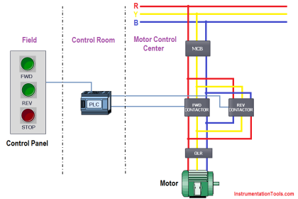
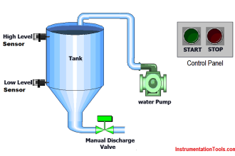
A engineer needs to write a PLC program to control a water pump driven by an electric motor. This water pump will be manually started and stopped by pushbutton switches, and shut down automatically by any one of several “permissive” switches.
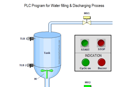
PLC Program to Control a Water Pump
The operating statuses of these switches are listed here:
- Start pushbutton (normally-open): open when unpressed, closed when pressed
- Stop pushbutton (normally-closed): closed when unpressed, open when pressed
- Low water level (normally-closed): closed when level is low, open when level is adequate
- Low oil pressure (normally-open): open when pressure is low, closed when pressure is adequate
- High vibration (normally-closed): closed when still, open when vibrating
- Water leak detector (normally-open): open when dry, closed when wet (leak detected)
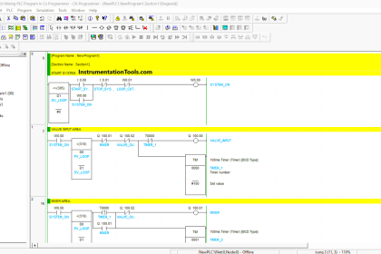
The engineers’s first attempt is shown here, but it contains a serious error. Identify and correct this error:
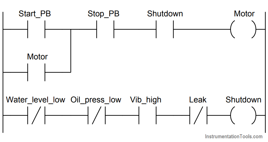
Answer :
The Oil_press_low contact instruction should be drawn as normally-open rather than normally-closed as shown in the engineer’s first draft of the PLC program.
The program is designed to shut down the motor if ever the Shutdown bit goes to a 0 state. This means the motor will shut down if any of the permissive contact instructions become uncolored (i.e. fails to “conduct” virtual power).
We have been told that the real-world oil pressure switch is NO, which means its contact opens when oil pressure becomes too low. This means a low oil pressure condition causes that bit to be 0, which necessitates an NO contact instruction so that it will un-color under that condition.
If you liked this article, then please subscribe to our YouTube Channel for PLC and SCADA video tutorials.
You can also follow us on Facebook and Twitter to receive daily updates.
More PLC Questions :