Inst ToolsInst ToolsInst Tools
  • Courses
  • Automation
    • PLC
    • Control System
    • Safety System
    • Communication
    • Fire & Gas System
  • Instrumentation
    • Design
    • Pressure
    • Temperature
    • Flow
    • Level
    • Vibration
    • Analyzer
    • Control Valve
    • Switch
    • Calibration
    • Erection & Commissioning
  • Interview
    • Instrumentation
    • Electrical
    • Electronics
    • Practical
  • Q&A
    • Instrumentation
    • Control System
    • Electrical
    • Electronics
    • Analog Electronics
    • Digital Electronics
    • Power Electronics
    • Microprocessor
  • Request
Search
  • Books
  • Software
  • Projects
  • Process
  • Tools
  • Basics
  • Formula
  • Power Plant
  • Root Cause Analysis
  • Electrical Basics
  • Animation
  • Standards
  • 4-20 mA Course
  • Siemens PLC Course
Reading: Gas Valve Sizing
Share
Font ResizerAa
Inst ToolsInst Tools
Font ResizerAa
  • Courses
  • Design
  • PLC
  • Interview
  • Control System
Search
  • Courses
  • Automation
    • PLC
    • Control System
    • Safety System
    • Communication
    • Fire & Gas System
  • Instrumentation
    • Design
    • Pressure
    • Temperature
    • Flow
    • Level
    • Vibration
    • Analyzer
    • Control Valve
    • Switch
    • Calibration
    • Erection & Commissioning
  • Interview
    • Instrumentation
    • Electrical
    • Electronics
    • Practical
  • Q&A
    • Instrumentation
    • Control System
    • Electrical
    • Electronics
    • Analog Electronics
    • Digital Electronics
    • Power Electronics
    • Microprocessor
  • Request
Follow US
All rights reserved. Reproduction in whole or in part without written permission is prohibited.
Inst Tools > Blog > Control Valves > Gas Valve Sizing

Gas Valve Sizing

Last updated: October 17, 2023 4:02 pm
Editorial Staff
Control Valves
No Comments
Share
3 Min Read
SHARE

Sizing a control valve for gas or vapor service is more complicated than for liquid service, due to the compressibility of gases and vapors.

As a gas or vapor compresses with changes in pressure, its density changes correspondingly. In previous mathematical analyses of fluid flow restriction, one of our assumptions was that fluid density (ρ) remained constant.

This assumption may hold true for some flowing gas conditions as well, provided minimal pressure changes within the path of flow.

However, for most gas control valve applications where the very purpose of the valve is to introduce substantial pressure changes, the assumption of constant gas density is unrealistic.

Gas Valve Sizing

Gas Valve Sizing

Shown here is one of the simpler gas valve sizing equations you will encounter:

gas valve sizing equations

Where,

Q = Gas flow rate, in units of Standard Cubic Feet per Hour (SCFH)
Cv = Valve capacity coefficient
ΔP = Pressure dropped across valve, pounds per square inch differential (PSID)
P1 = Upstream valve pressure, pounds per square inch absolute (PSIA)
P2 = Downstream valve pressure, pounds per square inch absolute (PSIA)
Gg = Specific gravity of gas (ratio of gas density to standard air density)
T = Absolute temperature of gas in degrees Rankine (oR), equal to degrees Fahrenheit plus 459.67

This equation holds true only for “subcritical” flow, where the moving gas stream velocity never approaches the speed of sound (Note). Other equations exist for calculating flow rates of gas through control valves in the presence of sonic flow regimes.

Note the inclusion of absolute pressures in this equation, and not just differential pressure (ΔP, or P1 − P2). This is intended to correct for effects related to compression of the gas under pressure.

Note : The ISA Handbook of Control Valves cites this equation as being valid for conditions where the valve’s downstream pressure (P2) is equal to or greater than one-half the upstream pressure (P1), with both pressures expressed in absolute units. In other words, P2 ≥ 0.5P1 or P1 ≤ 2P2. An upstream:downstream pressure ratio in excess of 2:1 usually means flow through a valve will become choked.

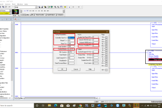
Valve sizing is complicated enough, both for liquid and gas service, that the use of valve sizing computer software is strongly recommended as opposed to hand-calculations.

The number of important parameters, nonlinear factors, and alternative equations relevant to control valve sizing are numerous enough to bewilder most technicians (and more than a few engineers).

Valve sizing software will also predict noise levels generated by the valve, and in many cases specify actual valve trim styles offered by the manufacturer for mitigating problems such as noise.

Also Read : Basics of Control Valve Sizing

Don't Miss Our Updates
Be the first to get exclusive content straight to your email.
We promise not to spam you. You can unsubscribe at any time.
Invalid email address
You've successfully subscribed !

Continue Reading

What is Double-ported Globe Valve ?
What is Pump Cavitation? How to Avoid Cavitation?
Root Cause Analysis for Tank Overflow due to Valve Problem
Free Control Valve Software Download
Basic Steps and Procedure for the Repair of Control Valve
Incident Investigation: Motor Operated Valve Lesson
Share This Article
Facebook Whatsapp Whatsapp LinkedIn Copy Link
Share
Leave a Comment

Leave a Reply Cancel reply

Your email address will not be published. Required fields are marked *

Stay Connected

128.3kFollowersLike
69.1kFollowersFollow
210kSubscribersSubscribe
38kFollowersFollow

Categories

Explore More

What is Cavitation? What are the Causes?
 Control Valve Accessories – Principle, Purpose, Advantages
Pilot-operated Safety and Relief Valves
Types of Check Valves
Valves MCQ
5 Port 2 Position Valve Working Principle
What is Complementary Split Range Control (CSRC)?
Basics of Globe Valves

Keep Learning

Control valve positioner calculation

Calculate Control Valve Stem Position

Volume Booster Working Principle

Control Valve Volume Booster Working Principle

Valve Technician Interview Questions

Valve Technician Interview Questions

Difference Between the Control Valve and Shut-off Valve

Difference Between the Control Valve and Shut-off Valve

Globe Valve Parts

What is Globe Valve ?

Self-actuated Temperature Regulator

Self-actuated Temperature Regulator – Principle, Types, Advantages

progressively sequenced control valves

Progressive Control Valve Sequence

Pressure Control Valve

What is Pressure Control Valve?

Learn More

instrumentation engineering standards

ISA codes for Process Instrumentation

Gas Compressor Seal Oil System

Gas Compressor Seal Oil System

Diesel Engine Fire Hydrant Pump

Fire Fighting System

Fire Extinguisher Operation

Basics of Fire Extinguisher

Pneumatic Level Control Valve

Piping and Instrumentation Drawing (P&ID) Tutorials – Part 3

Field Instruments Questions and Answers

Control Room and Field Instruments Questions and Answers

4-20mA Current Loop for Flow Transmitter and Control Valve Positioner

4–20 mA Process Control Loops

Programmable Logic Controller (PLC)

What is Interposing Relay in a PLC System ?

Menu

  • About
  • Privacy Policy
  • Copyright

Quick Links

  • Learn PLC
  • Helping Hand
  • Part Time Job

YouTube Subscribe

Follow US
All rights reserved. Reproduction in whole or in part without written permission is prohibited.
Welcome Back!

Sign in to your account

Username or Email Address
Password

Lost your password?