Particle image velocimetry (PIV) is an optical method of flow visualization used in education and research. It is used to obtain instantaneous velocity measurements and related properties in fluids.
The fluid is seeded with tracer particles which, for sufficiently small particles, are assumed to faithfully follow the flow dynamics (the degree to which the particles faithfully follow the flow is represented by the Stokes number). The fluid with entrained particles is illuminated so that particles are visible. The motion of the seeding particles is used to calculate speed and direction (the velocity field) of the flow being studied.
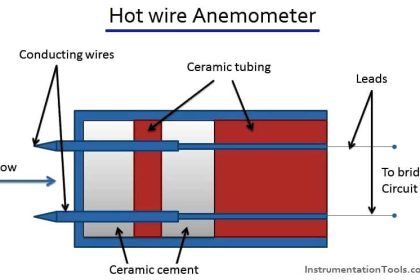
Other techniques used to measure flows are laser Doppler velocimetry and hot-wire anemometry. The main difference between PIV and those techniques is that PIV produces two-dimensional or even three-dimensional vector fields, while the other techniques measure the velocity at a point.
Particle Image Velocimetry (PIV)
During PIV, the particle concentration is such that it is possible to identify individual particles in an image, but not with certainty to track it between images. When the particle concentration is so low that it is possible to follow an individual particle it is called Particle tracking velocimetry, while Laser speckle velocimetry is used for cases where the particle concentration is so high that it is difficult to observe individual particles in an image.
Typical PIV apparatus consists of a camera (normally a digital camera with a CCD chip in modern systems), a strobe or laser with an optical arrangement to limit the physical region illuminated (normally a cylindrical lens to convert a light beam to a line), a synchronizer to act as an external trigger for control of the camera and laser, the seeding particles and the fluid under investigation.
A fiber optic cable or liquid light guide may connect the laser to the lens setup. PIV software is used to post-process the optical images.
Particle Image Velocimetry (PIV) is a whole-flow-field technique providing instantaneous velocity vector measurements in a cross-section of a flow.
Two velocity components are measured, but use of a stereoscopic approach permits all three velocity components to be recorded, resulting in instantaneous 3D velocity vectors for the whole area. The use of modern digital cameras and dedicated computing hardware, results in real-time velocity maps.
 Principle")
Advantages of Particle Image Velocimetry
- The technique is non-intrusive and measures the velocities of micron-sized particles following the flow.
- Velocity range from zero to supersonic.
- Instantaneous velocity vector maps in a cross-section of the flow.
- All three components may be obtained with the use of a stereoscopic arrangement.
- With sequences of velocity vector maps, statistics, spatial correlations and other relevant data are available.
Results are similar to computational fluid dynamics, i.e. large eddy simulations, and real-time velocity maps are an invaluable tool for fluid dynamics researchers.
Principle of Particle Image Velocimetry
In PIV, the velocity vectors are derived from sub-sections of the target area of the particle-seeded flow by measuring the movement of particles between two light pulses:
The flow is illuminated in the target area with a light sheet.
The camera lens images the target area onto the sensor array of a digital camera. The camera is able to capture each light pulse in separate image frames.
Once a sequence of two light pulses is recorded, the images are divided into small subsections called interrogation areas (IA). The interrogation areas from each image frame, I1 and I2, are cross-correlated with each other, pixel by pixel.
The correlation produces a signal peak, identifying the common particle displacement, DX. An accurate measure of the displacement – and thus also the velocity – is achieved with sub-pixel interpolation.
A velocity vector map over the whole target area is obtained by repeating the cross-correlation for each interrogation area over the two image frames captured by the camera.

The correlation of the two interrogation areas, I1 and I2 , results in the particle displacement DX, represented by a signal peak in the correlation C(DX).
PIV images are visual, just follow the seeding
Recording both light pulses in the same image frame to track the movements of the particles gives a clear visual sense of the flow structure. In air flows, the seeding particles are typically oil drops in the range 1 µm to 5 µm.
For water applications, the seeding is typically polystyrene, polyamide or hollow glass spheres in the range 5 µm to 100 µm. Any particle that follows the flow satisfactorily and scatters enough light to be captured by the camera can be used.
The number of particles in the flow is of some importance in obtaining a good signal peak in the cross-correlation. As a rule of thumb, 10 to 25 particle images should be seen in each interrogation area.

Fig: Double-pulsed particle images.
When the size of the interrogation area, the magnification of the imaging and the light-sheet thickness are known, the measurement volume can be defined.
Drawbacks of Particle Image Velocimetry
In some cases, the particles will, due to their higher density, not perfectly follow the motion of the fluid (gas/liquid). If experiments are done in water, for instance, it is easily possible to find very cheap particles (e.g. plastic powder with a diameter of ~60 µm) with the same density as water.
If the density still does not fit, the density of the fluid can be tuned by increasing/ decreasing its temperature. This leads to slight changes in the Reynolds number, so the fluid velocity or the size of the experimental object has to be changed to account for this.
Particle image velocimetry methods will in general not be able to measure components along the z-axis (towards to/away from the camera). These components might not only be missed, they might also introduce an interference in the data for the x/y-components caused by parallax. These problems do not exist in Stereoscopic PIV, which uses two cameras to measure all three velocity components.
Since the resulting velocity vectors are based on cross-correlating the intensity distributions over small areas of the flow, the resulting velocity field is a spatially averaged representation of the actual velocity field. This obviously has consequences for the accuracy of spatial derivatives of the velocity field, vorticity, and spatial correlation functions that are often derived from PIV velocity fields.
PIV systems used in research often use class IV lasers and high-resolution, high-speed cameras, which bring cost and safety constraints.
Source: dantecdynamics
If you liked this article, then please subscribe to our YouTube Channel for Instrumentation, Electrical, PLC, and SCADA video tutorials.
You can also follow us on Facebook and Twitter to receive daily updates.
Read Next:
- Laser Doppler Anemometer
- Optical flow meter Principle
- Radar Level Sensor Effects
- Basics of Ultrasonic flow meter
- Different Types of Flow Meters