Up until this point, we have explored various types of instrumentation diagram, each one making reference to different instruments by lettered identifiers such as TT (Temperature Transmitter), PDT (Pressure Differential Transmitter), or FV (Flow Valve), without formally defining all the letters used to identify instruments. Part of the ISA 5.1 standard does exactly this, which is what we will now investigate.
Each instrument within an instrumented facility should have its own unique identifying tag consisting of a series of letters describing that instrument’s function, as well as a number identifying the particular loop it belongs to. An optional numerical prefix typically designates the larger area of the facility in which the loop resides, and an optional alphabetical suffix designates multiple instances of instruments within one loop.
For example, if we were to see an instrument bearing the tag FC-135, we would know it was a flow controller (FC) for loop number 135. In a large manufacturing facility with multiple processing “unit” areas, a tag such as this might be preceded by another number designating the unit area. For example, our hypothetical flow controller might be labeled 12-FC-135 (flow controller for loop #135, located in unit #12). If this loop happened to contain multiple controllers, we would need to distinguish them from each other by the use of suffix letters appended to the loop number (e.g. 12-FC-135A, 12-FC-135B, 12-FC-135C).
Each and every instrument within a particular loop is first defined by the variable that loop seeks to sense or control, regardless of the physical construction of the instrument itself. Our hypothetical flow controller FC-135, for example, may be physically identical to the level controller in loop #72 (LC-72), or to the temperature controller in loop #288 (TC-288). What makes FC-135 a flow controller is the fact that the transmitter sensing the main process variable measures flow. Likewise, the identifying tag for every other instrument within that loop must begin with the letter “F” as well. This includes the final control element as well: in a level control loop, the transmitter is identified as an “LT” even if the actual sensing element works on pressure (because the variable that the loop strives to sense or control is actually level, despite the fact that liquid level is being inferred from pressure), the controller is identified as an “LC”, and the control valve throttling fluid flow is identified as an “LV”: every instrument in that level-controlling loop serves to help control level, and so its primary function is to be a “level” instrument.
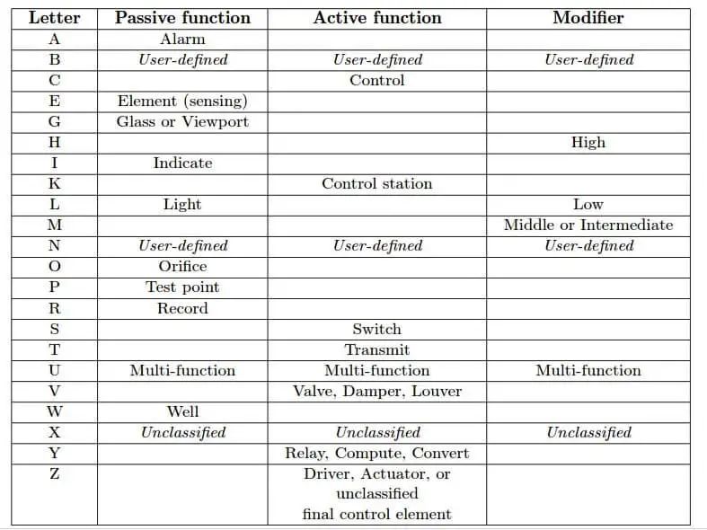
Valid letters recognized by the ISA for defining the primary process variable of an instrument within a loop are shown in the following table. Please note that the use of a modifier defines a unique variable: for example, a “PT” is a transmitter measuring pressure at a single point in a process, whereas a “PDT” is a transmitter measuring a pressure difference between two points in a process. Likewise, a “TC” is a controller controlling temperature, whereas a “TKC” is a controller controlling the rate-of-change of temperature:
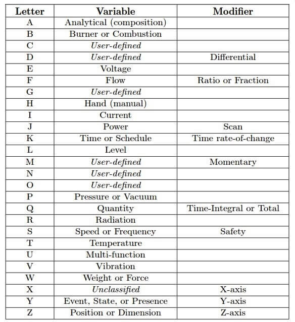
A “user-defined” letter represents a non-standard variable used multiple times in an instrumentation system. For example, an engineer designing an instrument system for measuring and controlling the refractive index of a liquid might choose to use the letter “C” for this variable. Thus, a refractive-index transmitter would be designated “CT” and a control valve for the refractive index loop would be designated “CV”. The meaning of a user-defined variable need only be defined in one location (e.g. in a legend for the diagram).
An “unclassified” letter represents one or more non-standard variables, each used only once (or a very limited number of times) in an instrumentation system. The meaning of an unclassified variable is best described immediately near the instrument’s symbol rather than in a legend.
Succeeding letters in an instrument tag describe the function that instrument performs relative to the process variable. For example, a “PT” is an instrument transmitting a signal representing pressure, while a “PI” is an indicator for pressure and a “PC” is a controller for pressure. Many instruments have multiple functions designated by multiple letters, such as a TRC (Temperature Recording Controller ). In such cases, the first function letter represents the “passive” function (usually provided to a human operator) while the second letter represents the “active” (automated) control function.
A variety of other letter combinations are often used to identify details not standardized bthe ISA. For example, chemical analyzer instruments often have their sample tube connections represented by the letter combination “SC,” although this does not appear anywhere in the ISA 5standard.
Some examples of instrument tag letters are shown in the following list:
• AIT = Analytical Indicating Transmitter (e.g. an oxygen concentration analyzer with a builtin display of oxygen percentage)
• ESL = Voltage Switch, Low (e.g. a switch used to detect an under-voltage condition in an electrical power system)
• FFI = Flow Ratio Indicator (e.g. a device indicating the ratio between air and fuel for a large industrial engine)
• FIC = Flow Indicating Controller (i.e. a controller designed to indicate flow to a human operator)
• HC = Hand Controller (i.e. a device allowing a human operator to set a control signal to some desired level, usually to operate a valve or other final control element)
• JQR = Power Totalizing Recorder (e.g. a watt-hour recorder, tracking total energy used)
• LSHH = Level Switch, High-High (e.g. a level-sensing switch designed to detect a dangerously high liquid level and initiate an automatic shutdown in that event)
• LT = Level Transmitter (i.e. a device sensing liquid level and reporting that level in some analog or digital form)
• PIT = Pressure Indicating Transmitter (e.g. a Rosemount model 3051 pressure transmitter with a built-in display of measured pressure)
• PDT = Pressure Differential Transmitter (i.e. a pressure transmitter built and installed to sense the difference of pressure between two points in a fluid system)
• PV = Pressure Valve (i.e. a control valve installed in a loop where the process variable is pressure)
• TE = Temperature Element (i.e. a sensing element used to directly detect the temperature of a process material; e.g. a thermocouple, thermistor, filled-bulb, bimetallic spring)
• TKAH = Temperature Rate-of-change Alarm, High (i.e. a device alarming when the rate of temperature change exceeds a pre-set limit)
• TV = Temperature Valve (i.e. a control valve installed in a loop where the process variable is temperature)
• TY = Temperature Converter (e.g. an I/P transducer in a temperature loop)
• VSH = Vibration Switch, High (i.e. a switch used to detect a high level of vibration on a piece of machinery)
• ZXI, ZYI, and ZZI = Position Indicators for X, Y, and Z axes respectively (e.g. indicators showing the three axis positions for a CNC machine tool)