Inst ToolsInst ToolsInst Tools
  • Courses
  • Videos
  • Q & A
    • Interview
      • Instrumentation
      • Electronics
      • Electrical
      • Practical Questions
    • MCQ
      • Instrumentation MCQ
      • Electrical MCQ
      • Electronics MCQ
      • Control Systems MCQ
      • Analog Electronics MCQ
      • Digital Electronics MCQ
      • Power Electronics MCQ
      • Microprocessor MCQ
      • Multiple Choice Questions
  • EE
    • Electronics
      • Electronics Q & A
      • Electronic Basics
      • Electronic Devices & Circuits
      • Electronics Animation
      • Digital Electronics
    • Electrical
      • Electrical Basics
      • Electrical Q & A
      • Power Electronics
      • Electrical Machines
      • Electrical Animation
      • Power Systems
      • Switchgear & Protection
      • Transmission & Distribution
  • Measure
    • Control Valves
    • Calibration
    • Temperature
    • Pressure
    • Flow
    • Level
    • Analyzers
    • Switches
    • Vibration
    • Solenoid Valve
  • Control
    • PLC Tutorials
    • Control Systems
    • Safety Instrumented System (SIS)
    • Communication
    • Fire & Gas System
  • More
    • Design
    • Tools
    • Animation
    • Basics
    • Formulas
    • Standards
    • TextBooks
    • Common
    • Software
    • Excel Tools
    • Erection & Commissioning
    • Process Fundamentals
    • Videos
    • Books
Search
All rights reserved. Reproduction in whole or in part without written permission is prohibited.
Reading: P&ID Guidelines for Centrifugal Compressor Systems
Share
Notification Show More
Font ResizerAa
Inst ToolsInst Tools
Font ResizerAa
  • Courses
  • PLC Tutorials
  • Control Systems
Search
  • Courses
  • Videos
  • Q & A
    • Interview
    • MCQ
  • EE
    • Electronics
    • Electrical
  • Measure
    • Control Valves
    • Calibration
    • Temperature
    • Pressure
    • Flow
    • Level
    • Analyzers
    • Switches
    • Vibration
    • Solenoid Valve
  • Control
    • PLC Tutorials
    • Control Systems
    • Safety Instrumented System (SIS)
    • Communication
    • Fire & Gas System
  • More
    • Design
    • Tools
    • Animation
    • Basics
    • Formulas
    • Standards
    • TextBooks
    • Common
    • Software
    • Excel Tools
    • Erection & Commissioning
    • Process Fundamentals
    • Videos
    • Books
Follow US
All rights reserved. Reproduction in whole or in part without written permission is prohibited.
Inst Tools > Blog > Erection & Commissioning > P&ID Guidelines for Centrifugal Compressor Systems

P&ID Guidelines for Centrifugal Compressor Systems

Last updated: June 20, 2019 9:48 am
Editorial Staff
Erection & Commissioning
No Comments
Share
6 Min Read
SHARE

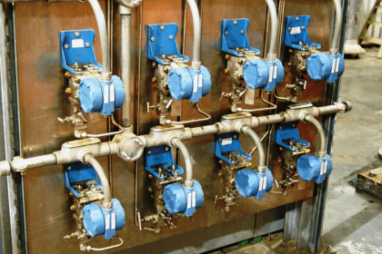
Typical P&ID for a centrifugal compressor system

P&ID Guidelines for Centrifugal Compressor Systems

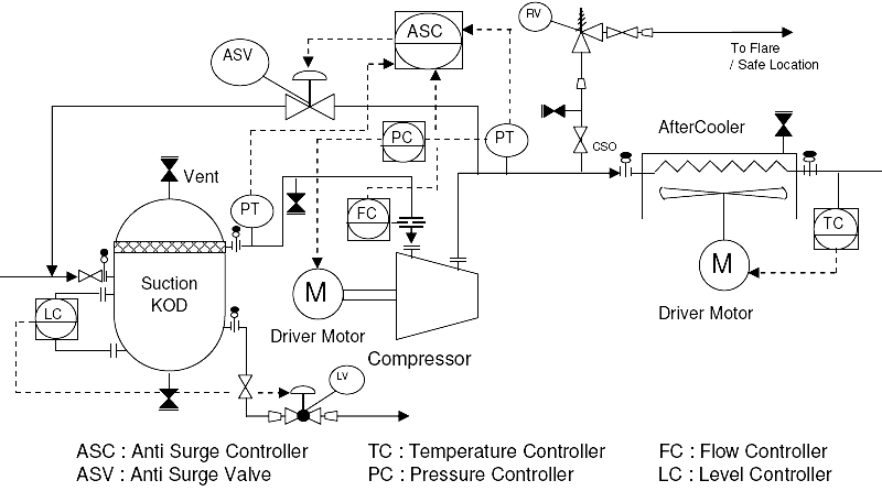
    1. Proper centrifugal compressor symbol should be selected first, as shown in figure-1. Normally, a centrifugal compressor is accompanied by a Knock Out Drum (KOD) at the compressor suction and an aftercooler at the compressor discharge, as per a typical compressor PFD. Symbols for these equipments should also be placed on the P&ID before proceeding ahead. All the equipment symbols should be selected from the legend sheets of a particular project.
    2. All the nozzles on the compressor, suction drums and aftercooler should then be correctly represented with size and flanges. This includes inlet and outlet nozzles and equipment drains / vents as shown in the typical P&ID in figure-1.
    3. Centrifugal compressor suction KOD is intended for removing the entrained liquids before sending gas to the compressor. Demister, mesh pad etc. are used in the knock out drum to efficiently remove the liquid droplets.
    4. Compressor aftercoolers are generally air coolers and the related fan, motor etc. should be clearly indicated on the P&ID. If cooling water is used, proper symbol for a heat exchanger should be used.
    5. Inlet, outlet lines for each equipment, anti-surge line, drain/vent lines, line to the relief valve etc. are the next to be drawn up. Line number, material class, size etc. is to be correctly assigned to each of the lines.
    6. Isolation valves, spectacle blinds, spacers etc. to be used for maintenance should be drawn up next on various lines between the equipments. Requirement for isolation valves, spectacle blind, spaces etc. depend on the project standards, which should be followed while indicating these on the P&ID. Sometimes, to minimize the number of isolation valves between the equipment, they can be placed only at the suction KOD inlet which is inlet of the centrifugal compressor system and discharge of the aftercooler which turns out to be the outlet of the centrifugal compressor system. Spectacle blinds or spacers can be used for isolation between individual equipments for quick maintenance. This is simply a guideline and project standards need to be followed when indicating the isolation requirements.
    7. A check valve should be normally provided on the compressor discharge to avoid reverse flow when the pump is not in operation.
    8. Pressure relief valves can be provided on the compressor discharge line, downstream to the check valve, to protect the equipments downstream of compressor.
    9. Pressure gauges should be provided on suction and discharge of the compressor. Level gauges need to be located on the compressor suction knock out drum and temperature gauges on inlet, outlet lines for the aftercooler.
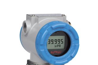
    10. Pressure transmitters should be provided on compressor suction and discharge line. A flow transmitter should be provided on compressor suction line. Signals from these transmitters are sent to an ‘Anti-Surge Controller’. Based on the gas flow and differential pressure head developed by the compressor, the anti-surge controller operates the anti-surge valves to prevent compressor surge condition.
    11. An anti-surge line from the aftercooler discharge to the suction KOD inlet should be provided for anti-surge control. When the compressor approaches surge condition (low flow, high differential head), the anti-surge valves open up to lower the pressure differential and circulate higher gas flow.
    12. Sometimes, a performance controller can be included in the centrifugal compressor system to control the rotating speed (RPM) of the compressor based on inlet pressure, flow etc. in order to achieve optimum performance. Performance controller will typically adjust the motor/turbine speed.
    13. Level transmitters provided on the suction knock out drum are responsible for liquid level control in the drum. Alarms are usually provided for high and high high liquid level conditions.
    14. Temperature transmitter can be provided on aftercooler for temperature control by sending a signal to adjust the fan speed of the aircooler.
    15. Emergency Shutdown (ESD) valves can be provided on inlet / outlet lines of the compressors system to isolate whole system in case of a shutdown. The inlet line of the suction KOD corresponds to inlet of the compressor system. Aftercooler discharge and liquid outlet of suction knock out drum correspond to the outlet lines of the compressor system. Shutdown valves can be located on these lines as shown in figure-1.
    16. Drains and vents to be provided on the suction / discharge lines, compressor casing, suction Knock Out Drum, air cooler body etc. for completely draining/venting compressor and associated piping, for maintenance.
    17. For purging the compressor system, a nitrogen connection can be provided right after the first isolation valve on the suction KOD inlet line.
    18. All the guidelines given here are very general and may be modified as per specific requirements of any particular project.
Don't Miss Our Updates
Be the first to get exclusive content straight to your email.
We promise not to spam you. You can unsubscribe at any time.
Invalid email address
You've successfully subscribed !

Recommended Articles

Gas Detectors Installation Techniques
Control Valves Pre-Commissioning Checklist
What is Process Flow Diagram (PFD) ?
What is Double Block and Bleed Valves?
Commissioning a Differential Pressure Transmitter in a Pressurized Boiler Steam Drum
How to Install Thermowell on an Elbow?
Share This Article
Facebook Whatsapp Whatsapp LinkedIn Copy Link
Share
Leave a Comment

Leave a Reply Cancel reply

Your email address will not be published. Required fields are marked *

Stay Connected

128.3kFollowersLike
69.1kFollowersFollow
208kSubscribersSubscribe
38kFollowersFollow

Categories

Recent Comments

  • William Snyder on Top Non-PLC Certification Courses for Automation Professionals
  • Kamli on Top Free PLC Software
  • Guifty Shimica on Top Non-PLC Certification Courses for Automation Professionals
  • Guifty Shimica on Top Non-PLC Certification Courses for Automation Professionals

Related Articles

Piping and Instrumentation Diagram

What is Piping and Instrumentation Diagram (P&ID) ?

Tips for Reducing the Noise Signals

Tips for Reducing the Noise Signals

Installation and Maintenance of Control Valves

Installation and Maintenance of Control Valves

Multiple Thermowell Installations Problems

Multiple Thermowell Installations Problems

P&ID arrangement for Control Valves

P&ID Guidelines for Control Valves

Installation Precautions of Thermocouple and RTD

Installation Precautions of Thermocouple and RTD

P&ID Guidelines for Storage Tanks

P&ID Guidelines for Storage Tanks

P&ID Guidelines for Pumps Heat Exchangers

P&ID Guidelines for Pumps Heat Exchangers

More Articles

Basic Concepts of the Safety Relay

Basic Concepts of the Safety Relay

Electrical Machines Questions and Answers

Ideal Two Winding Transformer

Hazardous Area Questions & Answers

Hazardous Area Classification Questions

Laser Diode Working Principle

Laser Diode Working Principle

Functional Safety Engineering

SIS Safety Requirements

Top 100 LabVIEW Projects for Engineering Students

Top 100 LabVIEW Projects for Engineering Students

SCADA Features

Features of SCADA

Deluge System for Transformer Protection

Deluge System for Transformer Protection Animation

Follow US
All rights reserved. Reproduction in whole or in part without written permission is prohibited.
Welcome Back!

Sign in to your account

Username or Email Address
Password

Lost your password?