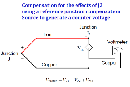
The thermocouple is used to measure the temperature, but the measurement is based on the temperature difference of hot and cold junction. The cold junction temperature can vary according to surrounding environment condition and, to nullify effect of cold junction temperature cold junction compensation is provided in the transmitter to get the absolute temperature.
Contrary to this, RTD measures the absolute temperature values. The RTD is preferred where low to medium range temperature to be measured.
One of the major error creeps in the measurement is the lead resistance error. We use triad cables (3 core) to connect the 3 wire RTD sensor and the respective transmitter. These cables resistance is called as lead wire resistance.
The transmitter and the RTD is mounted at the distinct location. The measurement error increase with increase of distance between the transmitter and the RTD position.
2 Wire RTD
The lead wire resistance gets added in the resistance of the RTD and thus the measurement error increase. The circuit diagram of 2 wire RTD is as given below.
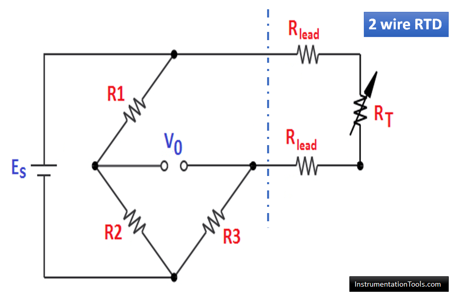
Here
- R1, R2, R3 are wheatstone bridge resistors
- Rlead is the resistance of that particular lead wire
- RT is the resistance of RTD
Under bridge balance condition
(R1/R2) = (Rx) / (R3)
Rx = (R1/R2)(R3)
Here Rx is the sum of RT and two lead wires resistance.
From above, it is clear that the lead resistance introduce error in measurement.
Example
The RTD model is PT 100. The temperature co-efficient of the RTD is 0.00385.
Case 1:
Assume we are measuring the resistance of RTD without any lead wires or directly at the terminals of 2 wire RTD.
Assume the temperature is 100 degree centigrade.
The resistance of RTD is 138.5 Ω
In this case, the measured resistance shows the correct temperature readings.
Case 2:
In practical applications, we use a cable to connect the RTD to the transmitter. This cable resistance is called lead wire resistance and it will add to the total resistance.
We use 2 lead wires to connect the RTD and transmitter. If each lead wire resistance is 1 Ω
Then the total resistance = RTD + (2 x Lead wire resistance)
Total Resistance = (138.5 + (2 x 1)) = 140.5 Ω
In this case, the temperature according to the total resistance value is 105.19 degree centigrade. Thus, the lead resistance introduced measurement error of 5.19 degree centigrade.
Use the RTD calculator for easy calculations. Do not forget to update the temperature co-efficient value as per the example.
3 Wire RTD
3 wire RTD measures more accurately than the 2 wire RTD. 3 Wire RTD is mostly used in temperature measurement for industrial applications.
Let us understand why 3 wires RTD reads more accurately than 2 wire RTD. The circuit diagram of 3 wire RTD is as shown below.
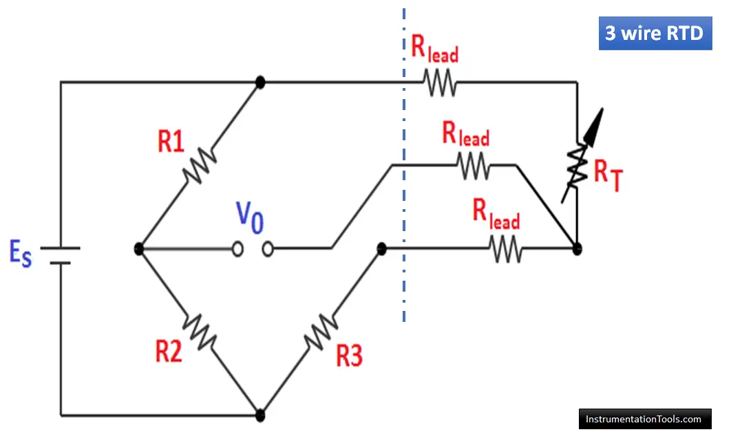
In simple terms, the wheatstone bridge equation is as follows
(R1/R2) = (RT+Rlead) / (R3 +Rlead)
In above equation, the numerator and denominator of right hand side part of the equation increase by Rlead and thus the ratio does not get affected due to lead resistance. Care must be taken to take the similar length of both the lead wires. Thus, the lead wires compensation can be done through 3 wire RTD.
Under bridge balance condition.
RT + Rlead = R3 + Rlead
RT = R3
In 3 wire RTD, the lead resistance Rlead will be cancelled each other with the help of a third lead wire. Thus the measurement does not get affected due to lead resistance.
Care must be taken to take the similar resistance of both the lead wires. Thus, the lead wires compensation can be done accurately through 3 wire RTD.
Also Read: 3 wire RTD Example Calculation
The lead wire resistance compensation is accurate only if all the lead wires resistance are equal. Otherwise, there will be error in temperature measurement on account of lead wire resistance mismatch.
4 Wire RTD
4 Wire RTD is used to completely eradicate the measurement error caused by wire resistance.
In 2 wire RTD and 3 wire RTD, the temperature measurement is affected because there is a change in RTD resistance due to lead wires. In both cases, the temperature measured based on the change in resistance. So we are getting the error. In 2 wire RTD, the error value is high and in 3 wire RTD the error value is very very less.
Why 4 wire RTD is Better?
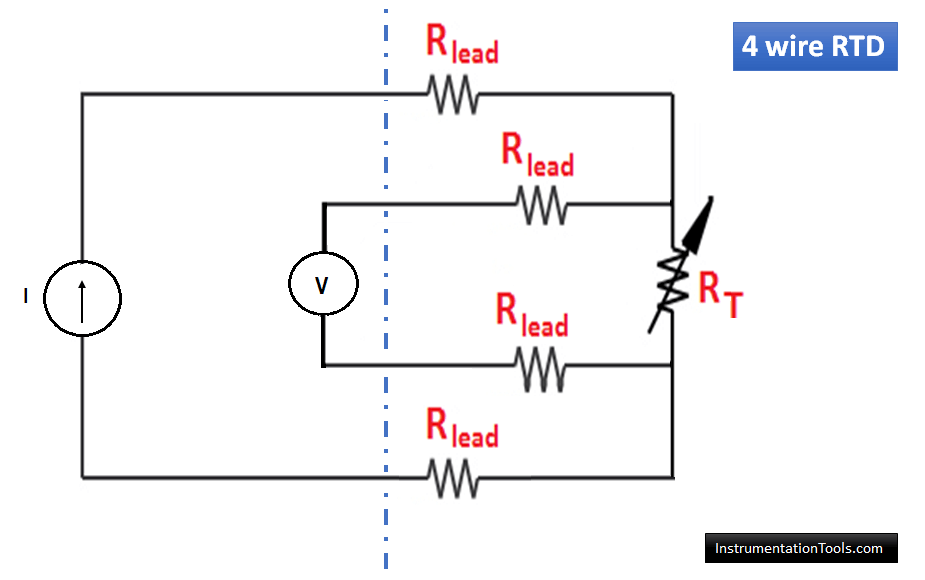
But in 4 wire RTD, we do not measure the temperature based on resistance. We use a constant current source in series with the two lead wires of 4 wire RTD. We measure the voltage drop across the another two lead wires of 4 wire RTD.
As per the ohms law, V = IR
The current value is constant here (very less). The voltage will be generated based on the change in resistance which in turns depends on the measured temperature.
That’s why 4 wire RTD is more accurate than the 2 or 3 wire RTD’s as the temperature measurement based on the voltage signal instead of resistance.
The circuit diagram of 4 wire RTD is as shown below.
4 wire RTD is used for temperature measurement in custody transfer meters, test laboratories where exact temperature readings are desired.
3 wire RTD cancel the lead resistance but it does not take care of lead wire resistance mismatch. The 4 wire RTD is used to completely eliminate the error caused by lead resistance mismatch even.
4 wire RTD system is more expensive than the 2 wire and 3 wire RTD, but is the best for those applications where a high degree of accuracy is required.
The only disadvantage of 4 wire RTD is that it may introduce a very very small amount of measurement error due to self-heating (because of flow of constant current through RTD) over a period of time. A periodic calibration is carried out to the transmitters for validating the measurement accuracy.
Conclusion
- 2 Wire RTD introduce more error in measuring because of lead resistance. 2 wire RTD is suitable if the transmitter is mounted in the vicinity of RTD.
- 3-wire RTD is suitable for industrial application. The lead wire compensation is possible in 3 wire temperature measurement system. The error caused by lead resistance is completely eliminated, however the lead resistance mismatch can cause error in measurement.
- 4 wire RTD is the best choice for the applications which requires precise temperature measurement.
Author: Satyadeo Vyas
If you liked this article, then please subscribe to our YouTube Channel for Instrumentation, PLC, and SCADA video tutorials.
You can also follow us on Facebook and Twitter to receive daily updates.
Read Next:


Sir 2 wire RtD example what is the temp at 139.24 ohm resistance….. How is temp 105.22 degree
How can I DL this article?
Than you
This article is incorrect. The Wheatstone bridge circuit shown for 2-wire and 3-wire measures the resistance buy measuring the voltage difference between the mid-point of the right side of the bridge (the voltage at this point is fixed as the two resistors have fixed values) and the mid-point of the left side of the bridge (the voltage can change as there is one fixed resistor and the RTD element, whose resistance changes based on temperature).
The 4-wire RTD measurement uses a constant current passed through the RTD element via the two excitation wires. The current remains constant even though the resistance of the RTD changes with temperature. The current also remains constant if the resistance of the two excitation wires is different, either due to different length or cress section area, or a bad connection, up to a point. The two sensing wires measure the voltage across the RTD element back to the measuring circuit, which always has a very high input impedance, so the resistance of the sensing wires themselves is negligible compared to the high input impedance of the circuit.
Both the bridge circuits used for the 2-wire and 3-wire RTD, and the constant current circuit used by the 4-wire RTD measure the resistance of the the RTD by passing a current through it and measuring the voltage, so it isn’t correct to say the the 2-wire and 3-wire measure resistance and the 4-wire measures voltage. The 4-wire RTD measuring circuit is better because it uses a constant excitation current, which tolerates some level of resistance difference between the connecting wires without adversely affecting the reading, whereas the bridge circuit does not.