This article discusses controlling the Exhaust FAN automatically using a timer in the XG-5000 PLC software.
Automatic Exhaust Fan
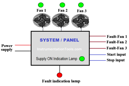
The Exhaust FAN PLC program is used to suck up dust in the room. The system can be Run in 2 modes, Auto or Timer. In Auto mode, the Exhaust Fan will turn ON when the dust level in the room exceeds the “Set value” limit.
When the system is Running in Timer mode, the Exhaust Fan will turn ON sequentially. Exhaust Fan will be ON for 5 seconds and will be OFF for 5 seconds.
This PLC program uses 2 buttons and 1 selector switch, the START_SYSTEM (P0000) button is used to Turn ON the system, and the STOP_SYSTEM (P0001) button is used to Turn OFF the system.
Selector Switch MODE_BUTTON (P0002) is used to select the system to Run in Auto or Timer mode.
By default, when the START_SYSTEM (P0000) button is pressed, the system will Run in Auto Mode. The Output OUT_FAN (P0040) will be ON when the value in the memory word PV_TEMPERATURE (M050) is greater than or equal to the memory word SV_TEMPERATURE (M051).
When Selector Switch MODE_BUTTON (P0002) is changed to Timer mode, the Output OUT_FAN (P0040) will be ON for 5 seconds and then OFF repeatedly.
The system will be OFF if the STOP_SYSTEM (P0001) button is Pressed.
Program IO
| Comment | Input (I) | Output (Q) | Memory Bits | Memory Word | Timers |
| START_SYSTEM_SYSTEM | P0000 | ||||
| STOP_SYSTEM_SYSTEM | P0001 | ||||
| MODE_BUTTON | P0002 | ||||
| OUT_FAN | P0040 | ||||
| SYSTEM_ON | M0000 | ||||
| TIMER_MODE | M0001 | ||||
| AUTO_MODE | M0002 | ||||
| TIMER_MODE | M0003 | ||||
| AUTO_MODE | M0005 | ||||
| PV_TEMPERATURE | M050 | ||||
| SV_TEMPERATURE | M051 | ||||
| TIMER_1 | T000 | ||||
| TIMER_2 | T001 |
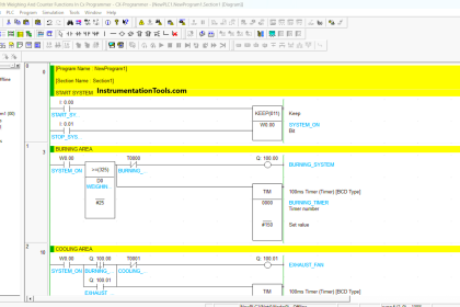
XG5000 PLC Programming
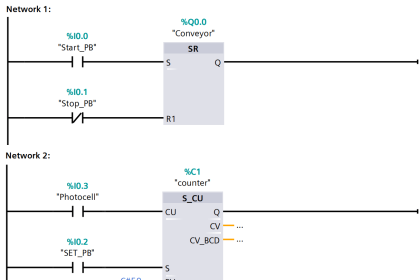
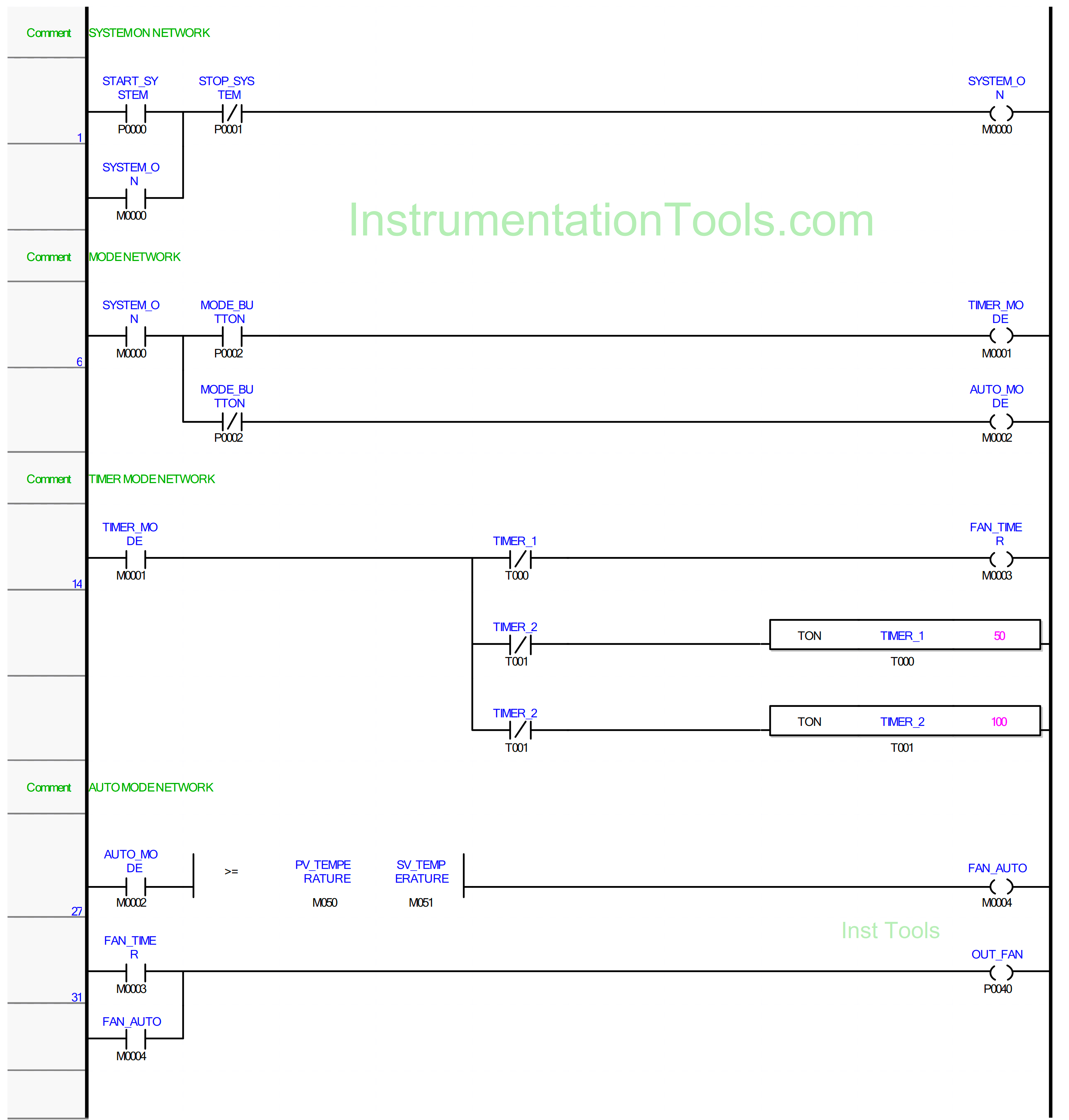
NETWORK 1
In this rung, when the START_SYSTEM (P0000) button is pressed, the memory bit SYSTEM_ON (M0000) will be in the HIGH state. Memory bit SYSTEM_ON (M0000) will remain in the HIGH state even though the START_SYSTEM (P0000) button has been Released because it uses Latching.
If the STOP_SYSTEM (P0001) button is Pressed, the memory bit SYSTEM_ON (M0000) will change to LOW state.
NETWORKS 6
When the NO contact of memory bit SYSTEM_ON (M0000) is HIGH and the NC contact of Selector Switch MODE_BUTTON (P0002) is in the LOW state, the memory bit AUTO_MODE (M0002) will be in the HIGH state.
The memory bit TIMER_MODE (M0001) will be in HIGH state if the NO contact of memory bit SYSTEM_ON (M0000) and the NO contact of Selector Switch MODE_BUTTON (P0002) are in HIGH state.
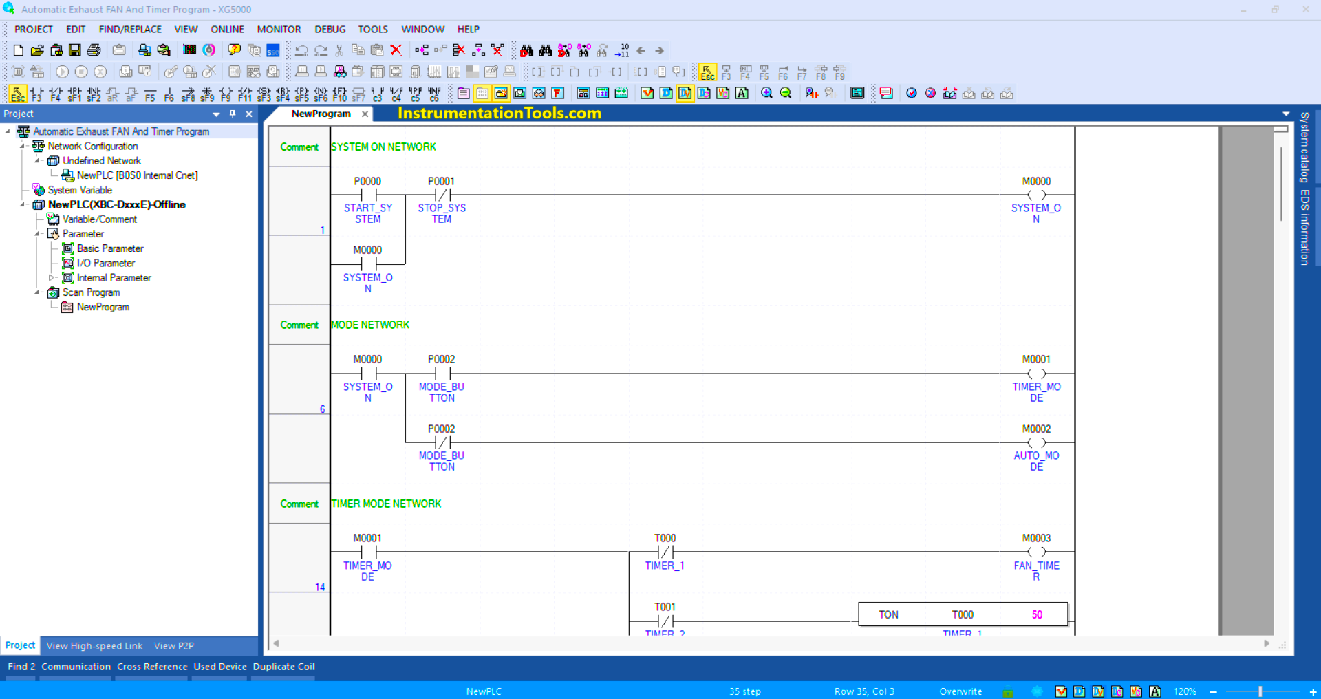
NETWORKS 14
In this Rung, when the NO contact of memory bit SYSTEM_ON (M0000) is in the HIGH state, the memory bit FAN_TIMER (M0003) will be in the HIGH state. The timer instruction TIMER_1 (T000) will start counting up to 5 seconds and TIMER_2 (T001) will count up to 10 seconds.
When the timer TIMER_1 (T000) finishes counting, the memory bit FAN_TIMER (M0003) will change to a LOW state due to the interlock of the timer TIMER_1 (T000).
When the TIMER_2 (T001) timer finishes counting, the timer TIMER_1 (T000) will be OFF due to the interlock of timer TIMER_2 (T002) and memory bit FAN_TIMER (M0003) will change to a HIGH state again.
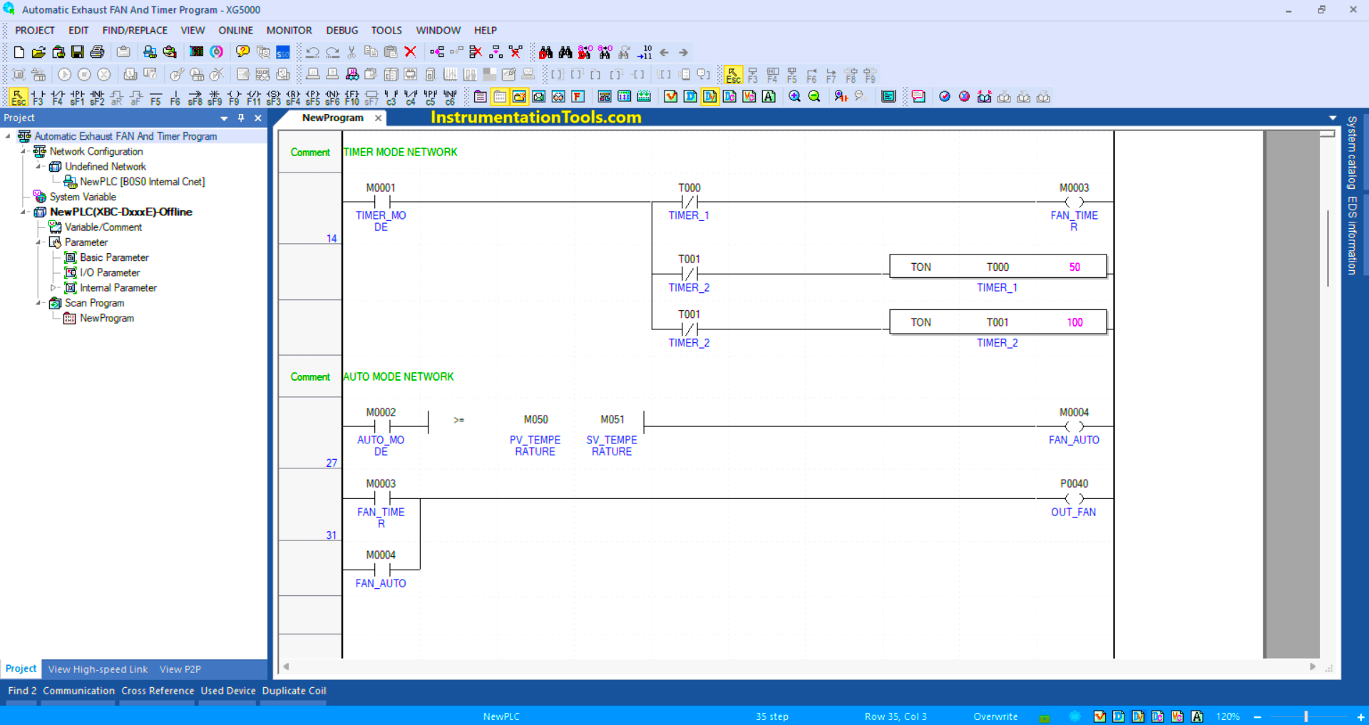
NETWORKS 27
In this Rung, when the NO contact of memory bit SYSTEM_ON (M0000) is in a HIGH state and the value in memory word PV_TEMPERATURE (M050) is greater than or equal to memory word SV_TEMPERATURE (M051), then the memory bit FAN_AUTO (M0004) will be in the HIGH state.
When the value in the memory word PV_TEMPERATURE (M050) is Less than the memory word SV_TEMPERATURE (M051), then the memory bit FAN_AUTO (M0004) will be in LOW state.
NETWORKS 31
The Output OUT_FAN (P0040) will be ON if the NO contact of memory bit FAN_TIMER (M0003) or FAN_AUTO (M0004) is in the HIGH state.
Read Next:
- Automatic Vacuum Cleaner PLC Programming
- STAR-DELTA Auto And Manual PLC Program
- Electric Motor Forward Reverse PLC Logic
- Product Painting with Omron PLC Program
- Attendance System Program in Omron PLC