Inst ToolsInst ToolsInst Tools
  • Courses
  • Automation
    • PLC
    • Control System
    • Safety System
    • Communication
    • Fire & Gas System
  • Instrumentation
    • Design
    • Pressure
    • Temperature
    • Flow
    • Level
    • Vibration
    • Analyzer
    • Control Valve
    • Switch
    • Calibration
    • Erection & Commissioning
  • Interview
    • Instrumentation
    • Electrical
    • Electronics
    • Practical
  • Q&A
    • Instrumentation
    • Control System
    • Electrical
    • Electronics
    • Analog Electronics
    • Digital Electronics
    • Power Electronics
    • Microprocessor
  • Request
Search
  • Books
  • Software
  • Projects
  • Process
  • Tools
  • Basics
  • Formula
  • Power Plant
  • Root Cause Analysis
  • Electrical Basics
  • Animation
  • Standards
  • 4-20 mA Course
  • Siemens PLC Course
Reading: What is PV Tracking ?
Share
Font ResizerAa
Inst ToolsInst Tools
Font ResizerAa
  • Courses
  • Design
  • PLC
  • Interview
  • Control System
Search
  • Courses
  • Automation
    • PLC
    • Control System
    • Safety System
    • Communication
    • Fire & Gas System
  • Instrumentation
    • Design
    • Pressure
    • Temperature
    • Flow
    • Level
    • Vibration
    • Analyzer
    • Control Valve
    • Switch
    • Calibration
    • Erection & Commissioning
  • Interview
    • Instrumentation
    • Electrical
    • Electronics
    • Practical
  • Q&A
    • Instrumentation
    • Control System
    • Electrical
    • Electronics
    • Analog Electronics
    • Digital Electronics
    • Power Electronics
    • Microprocessor
  • Request
Follow US
All rights reserved. Reproduction in whole or in part without written permission is prohibited.
Inst Tools > Blog > Control Systems > What is PV Tracking ?

What is PV Tracking ?

Last updated: October 9, 2018 4:17 pm
Editorial Staff
Control Systems
1 Comment
Share
2 Min Read
SHARE

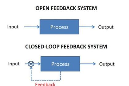
Setpoint Tracking (also called PV tracking):

PV Tracking is An option on many controllers. When a control loop is in MANUAL, with PV Tracking turned on, the controller setpoint (SP) will follow the PV. When the loop is returned to AUTO, there is no sudden movement of the process, because the PV is already at setpoint. If PV Tracking is turned off, returning to AUTO will drive the loop to its previous setpoint.

Setpoint tracking refers to the automatic adjustment of the controller setpoint so that it follows the process variable (PV). This occurs (only if the option is enabled) when the controller is in the manual mode. If set point tracking is enabled,when the controller is transferred to auto, the transfer takes place without any change whatsoever in controller output. This also means of course that the loop will continue to adjust the final element to maintain the PV at the value obtaining immediately before the transfer to auto. This may not be desirable in all cases since it relies on the operator to readjust the setpoint to the desired value at some time after the controller is transferred to auto.

Typical applications where setpoint tracking is desirable are those where the setpoint may vary under normal circumstances e.g. fuel gas flow on a boiler. In applications where the setpoint is normally fixed e.g. for steam temperature control, setpoint tracking would not normally be enabled.

Most often it is referred to as providing bumpless transfer from manual to auto. Without setpoint tracking whether or not a bump occurs depends on the state of tune of the controller. Since in manual, the controller integral term initializes so that the sum of the integral and proportional terms equals the manual output value, when the controller is trasferred to auto, there is no step due to proportional action but the output initially ramps at a rate proportional to the gain*error/integral action time.

Also Read: PID Controller Bumpless Transfer

Don't Miss Our Updates
Be the first to get exclusive content straight to your email.
We promise not to spam you. You can unsubscribe at any time.
Invalid email address
You've successfully subscribed !

Continue Reading

Emergency Stop Switch Spurious Trip
All About Fieldbus Protocols
Derivative Controller Principle
Integrating Processes – Liquid Level Control
How to Write a Program in Ecostruxure Machine Expert HVAC Software?
Troubleshooting a 4-20mA Current loop
Share This Article
Facebook Whatsapp Whatsapp LinkedIn Copy Link
Share
1 Comment
  • Allanso Golden says:
    January 19, 2021 at 7:26 am

    I want this knowledge

    Reply

Leave a Reply Cancel reply

Your email address will not be published. Required fields are marked *

Stay Connected

128.3kFollowersLike
69.1kFollowersFollow
210kSubscribersSubscribe
38kFollowersFollow

Categories

Explore More

Introduction to PlantPAx Distributed Control System
Closed Loop Control System : Boiler Water Level Control System
Free PID Controller Gains Tuning Tool
Instrumentation and Control (I&C) Design
PID Controller Functions
Modbus Function Command Formats
BPCS Control System and ESD Safety System of Delta-V DCS
How to Stop Cyber Attacks on PLC or DCS?

Keep Learning

HMI

Learn about SCADA and HMI Systems

How to Train Your Maintenance Team for Industrial Automation Systems

How to Train Your Maintenance Team for Industrial Automation Systems?

Augmented Reality and Virtual Reality in Industrial Automation

Augmented Reality and Virtual Reality in Industrial Automation

Loop Calibrator to Simulate a 4-20 mA Signal

Loop Calibrator to Simulate a 4-20 mA Signal

Process Control System

Basics of Process Control Systems

Analog inputs in library

Design Process Graphics in Factory Talk View Studio with an Analog Input

Power Supply Sizing for Industrial Automation Systems

Power Supply Sizing for Industrial Automation Systems

IACS Network

Remote Connectivity to Industrial Automation Systems

Learn More

schottky diode working principle

Schottky Diode Working Principle

BUS TIE REACTORS

Current Limiting Reactors in Power System

Allen Bradley SLC 500 PLC Programming

Combining Independent Current Sources in Parallel

Combining Independent Current Sources in Parallel

Networked SCADA Architecture

Types of SCADA System Architecture

Difference between MCB and RCBO

Difference Between MCB and RCBO

Resistance Temperature Detectors Troubleshooting Tips

Resistance Temperature Detectors Troubleshooting Tips

Comparison of Control Loops - Open, Closed, Cascade, Feedforward, Ratio

Comparison of Control Loops – Open, Closed, Cascade, Feedforward, Ratio

Menu

  • About
  • Privacy Policy
  • Copyright

Quick Links

  • Learn PLC
  • Helping Hand
  • Part Time Job

YouTube Subscribe

Follow US
All rights reserved. Reproduction in whole or in part without written permission is prohibited.
Welcome Back!

Sign in to your account

Username or Email Address
Password

Lost your password?