Inst ToolsInst ToolsInst Tools
  • Courses
  • Automation
    • PLC
    • Control System
    • Safety System
    • Communication
    • Fire & Gas System
  • Instrumentation
    • Design
    • Pressure
    • Temperature
    • Flow
    • Level
    • Vibration
    • Analyzer
    • Control Valve
    • Switch
    • Calibration
    • Erection & Commissioning
  • Interview
    • Instrumentation
    • Electrical
    • Electronics
    • Practical
  • Q&A
    • Instrumentation
    • Control System
    • Electrical
    • Electronics
    • Analog Electronics
    • Digital Electronics
    • Power Electronics
    • Microprocessor
  • Request
Search
  • Books
  • Software
  • Projects
  • Process
  • Tools
  • Basics
  • Formula
  • Power Plant
  • Root Cause Analysis
  • Electrical Basics
  • Animation
  • Standards
  • 4-20 mA Course
  • Siemens PLC Course
Reading: What is LVDT ?
Share
Font ResizerAa
Inst ToolsInst Tools
Font ResizerAa
  • Courses
  • Design
  • PLC
  • Interview
  • Control System
Search
  • Courses
  • Automation
    • PLC
    • Control System
    • Safety System
    • Communication
    • Fire & Gas System
  • Instrumentation
    • Design
    • Pressure
    • Temperature
    • Flow
    • Level
    • Vibration
    • Analyzer
    • Control Valve
    • Switch
    • Calibration
    • Erection & Commissioning
  • Interview
    • Instrumentation
    • Electrical
    • Electronics
    • Practical
  • Q&A
    • Instrumentation
    • Control System
    • Electrical
    • Electronics
    • Analog Electronics
    • Digital Electronics
    • Power Electronics
    • Microprocessor
  • Request
Follow US
All rights reserved. Reproduction in whole or in part without written permission is prohibited.
Inst Tools > Blog > Pressure Measurement > What is LVDT ?

What is LVDT ?

Last updated: October 25, 2019 9:27 pm
Editorial Staff
Pressure Measurement
No Comments
Share
4 Min Read
SHARE

Linear Variable Displacement Transducer (LVDT):

A very basic transducer which is always useful in the field of instrumentation, I have studied about this in my college days.

Now let me explain about the LVDT with its Principle of Operation and I will explain how it is constructed for its well known operation and you can understand the working of LVDT.

Principle of LVDT:

LVDT works under the principle of mutual induction, and the displacement which is a non-electrical energy is converted into an electrical energy.

And the way how the energy is getting converted is described in working of LVDT in a detailed manner.

Construction of LVDT:

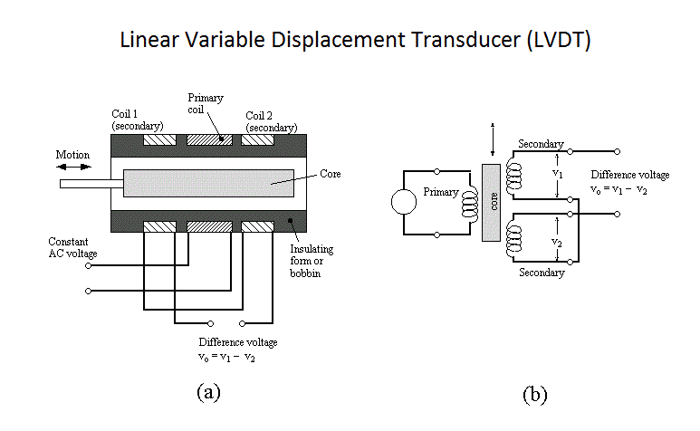
Linear Variable Displacement Transducer (LVDT)

LVDT consists of a cylindrical former where it is surrounded by one primary winding in the centre of the former and the two secondary windings at the sides.

The number of turns in both the secondary windings are equal, but they are opposite to each other, i.e., if the left secondary windings is in the clockwise direction, the right secondary windings will be in the anti-clockwise direction, hence the net output voltages will be the difference in voltages between the two secondary coil.

The two secondary coil is represented as S1 and S2. Esteem iron core is placed in the centre of the cylindrical former which can move in to and fro motion as shown in the figure.

The AC excitation voltage is 5 to 12V and the operating frequency is given by 50 to 400 HZ.

Also See : LVDT Working Animation

Working of LVDT:

Let’s study the working of LVDT by splitting the cases into 3 based on the iron core position inside the insulated former.

Case 1:

On applying an external force which is the displacement, if the core reminds in the null position itself without providing any movement then the voltage induced in both the secondary windings are equal which results in net output is equal to zero

i.e., Esec1-Esec2=0

Case 2:

When an external force is appilied and if the steel iron core tends to move in the left hand side direction then the emf voltage induced in the secondary coil is greater when compared to the emf induced in the secondary coil 2. Therefore the net output will be Esec1-Esec2

Case 3:

When an external force is applied and if the steel iron core moves in the right hand side direction then the emf induced in the secondary coil 2 is greater when compared to the emf voltage induced in the secondary coil 1. therefore the net output voltage will be Esec2-Esec1

Advantages of LVDT:

  • Infinite resolution is present in LVDT
  • High output
  • LVDT gives High sensitivity
  • Very good linearity
  • Ruggedness
  • LVDT Provides Less friction
  • Low hysteresis
  • LVDT gives Low power consumption.

Disadvantages of LVDT:

  • Very high displacement is required for generating high voltages.
  • Shielding is required since it is sensitive to magnetic field.
  • The performance of the transducer gets affected by vibrations
  • Its is greatly affected by temperature changes.

Applications of LVDT:

  • LVDT is used to measure displacement ranging from fraction millimeter to centimeter.
  • Acting as a secondary transducer, LVDT can be used as a device to measure force, weight and pressure, etc..
Don't Miss Our Updates
Be the first to get exclusive content straight to your email.
We promise not to spam you. You can unsubscribe at any time.
Invalid email address
You've successfully subscribed !

Continue Reading

How to Prepare Pressure Gauge Datasheet ?
Types of Pressure – Instrument Questions and Answers
Difference between Absolute, Gauge and Differential Pressure Transmitters
U-tube Manometer Principle
Interview Questions on Differential Pressure Flow Transmitter
PLC Raw Count Calculation for Pressure Transmitter
Share This Article
Facebook Whatsapp Whatsapp LinkedIn Copy Link
Share
Leave a Comment

Leave a Reply Cancel reply

Your email address will not be published. Required fields are marked *

Stay Connected

128.3kFollowersLike
69.1kFollowersFollow
210kSubscribersSubscribe
38kFollowersFollow

Categories

Explore More

McLeod Gauge Working Principle
5 Valve Manifold Operation
Pressure Gauge with Block and Bleed Valves
What is Static Pressure Limit in DP Transmitter ?
Installation and Calibration of Pressure Transmitter
15 HART Communicator Questions
What are Impulse Lines? – Impulse Line Problems & Solutions
Pressure Gauge Selection

Keep Learning

Differential Pressure Sensor for Filtration Monitoring

Differential Pressure Sensor for Filtration Monitoring

Strain Gauge Pressure Sensor Principle

Strain Gauge Pressure Sensor Principle

Instrument Protection Methods: Seals

Measuring process vessel clogging

DP Transmitter Applications

gauge’s bourdon tube

Pressure Gauges : Remote and Chemical Seals

Three Valve Manifold

3 Valve Manifold Operation

Pressure Transmitter Calibration Procedure

Pressure Transmitter Calibration Procedure

pressure gauge snubber

Pressure Gauge Snubbers

Learn More

What is Partial Stroke Test

What is Partial Stroke Test?

Digital Electronics Multiple Choice Questions

D Flip Flop Objective Questions

Function Block Diagram - Studio 5000 Logix Designer

Define the Order of Execution in Functional Block Diagram of Studio 5000

Motor ON OFF Logic in PLC

Motor ON OFF Logic in PLC

Bipolar Junction Transistor Construction

Bipolar Junction Transistor Construction

Feedback Characteristics of Control Systems

Linear Approximation of the Non-Linear System MCQ

Oscillating Piston Flow Meters Animation

Oscillating Piston Flow Meters Working Principle

Instrument Air Calculations

Basic Calculations of Instrument Air

Menu

  • About
  • Privacy Policy
  • Copyright

Quick Links

  • Learn PLC
  • Helping Hand
  • Part Time Job

YouTube Subscribe

Follow US
All rights reserved. Reproduction in whole or in part without written permission is prohibited.
Welcome Back!

Sign in to your account

Username or Email Address
Password

Lost your password?