By using this site, you agree to the Privacy Policy and Terms of Use.
Accept
Inst ToolsInst ToolsInst Tools
  • Ask
  • Courses
  • Videos
  • Q & A
    • Interview
      • Instrumentation
      • Electronics
      • Electrical
      • Practical Questions
    • MCQ
      • Instrumentation MCQ
      • Electrical MCQ
      • Electronics MCQ
      • Control Systems MCQ
      • Analog Electronics MCQ
      • Digital Electronics MCQ
      • Power Electronics MCQ
      • Microprocessor MCQ
      • Multiple Choice Questions
  • EE
    • Electronics
      • Electronics Q & A
      • Electronic Basics
      • Electronic Devices & Circuits
      • Electronics Animation
      • Digital Electronics
    • Electrical
      • Electrical Basics
      • Electrical Q & A
      • Power Electronics
      • Electrical Machines
      • Electrical Animation
      • Power Systems
      • Switchgear & Protection
      • Transmission & Distribution
  • Measure
    • Control Valves
    • Calibration
    • Temperature
    • Pressure
    • Flow
    • Level
    • Analyzers
    • Switches
    • Vibration
    • Solenoid Valve
  • Control
    • PLC Tutorials
    • Control Systems
    • Safety Instrumented System (SIS)
    • Communication
    • Fire & Gas System
  • More
    • Design
    • Tools
    • Animation
    • Basics
    • Formulas
    • Standards
    • TextBooks
    • Common
    • Software
    • Excel Tools
    • Erection & Commissioning
    • Process Fundamentals
    • Videos
    • Books
Search
All rights reserved. Reproduction in whole or in part without written permission is prohibited.
Reading: What is Integral Wind Up ?
Share
Notification Show More
Font ResizerAa
Inst ToolsInst Tools
Font ResizerAa
  • Ask
  • Courses
  • Videos
  • Q & A
  • EE
  • Measure
  • Control
  • More
Search
  • Ask
  • Courses
  • Videos
  • Q & A
    • Interview
    • MCQ
  • EE
    • Electronics
    • Electrical
  • Measure
    • Control Valves
    • Calibration
    • Temperature
    • Pressure
    • Flow
    • Level
    • Analyzers
    • Switches
    • Vibration
    • Solenoid Valve
  • Control
    • PLC Tutorials
    • Control Systems
    • Safety Instrumented System (SIS)
    • Communication
    • Fire & Gas System
  • More
    • Design
    • Tools
    • Animation
    • Basics
    • Formulas
    • Standards
    • TextBooks
    • Common
    • Software
    • Excel Tools
    • Erection & Commissioning
    • Process Fundamentals
    • Videos
    • Books
Follow US
All rights reserved. Reproduction in whole or in part without written permission is prohibited.
Inst Tools > Blog > Control Systems > What is Integral Wind Up ?

What is Integral Wind Up ?

Last updated: November 25, 2018 5:19 pm
Editorial Staff
Control Systems
2 Comments
Share
8 Min Read
SHARE

The PID controller plays a major role in controlling the process parameters in process industries. It consists of Proportional term, Integral term and Derivative term which combinedly reduces the transient error and steady state error. In steady state condition, i.e when the error tends to zero the output of PID is equal to the integral term of PID.

If the error = 0

then

 PID = Kc * error + Ki(previous integral + error) + Kd(error – last)

         =    0   +  Ki (previous integral + error)   + 0

          =   Ki (previous integral + error)

by the above analysis it is proved that the output of PID controller at the steady state is equal to integral term which acts as reset component of the controller. This illustrates the importance of integral controller in PID controller. With the advantage of reset rate of controller and minimizing the error to zero at steady state, there is major drawback in the integral term i.e wind-up of integral component.

Integral wind-up:

Integral windup is the process of accumulating the integral component beyond the saturation limits of final control element. The formula for integral component in PID is

Integral component = (Ts/Ti) * error

Where Ts = time cycle

           Ti  = Integral time constant or reset rate

If the set point raises suddenly or the actual value drops suddenly then there will be large error between the set-point and actual value. This error causes the integral component to accumulate with the time period to bring back the actual value near to the set-point. As a result the controller output may exceeds the saturation limits of final control element. The integral component still may accumulate beyond the saturation limits of the final control element because of error. Whatever the integral value the final element or actuator cannot open/close beyond its saturation value. This concept is explained by the following example

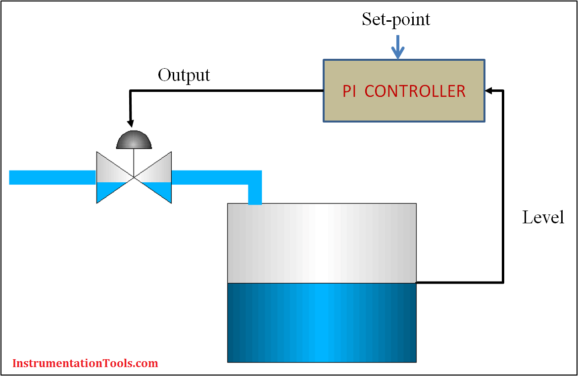
Consider a PI control is placed for controlling the liquid level in the controller which controls the inlet flow to the tank by adjusting the inlet valve position. Now if the set-point is raised by the operator from control room then the PI controller calculates the new actuator position according to the error. The integral component of the PI controller which adds the reset rate will accumulates according specified time cycles. If the output of PI controller is 120 % to the adjuster which is the above saturation limit of the actuator because actuator cannot open beyond 100 % position. In full position of valve also still if the error is existing will further increases the integral component value.

At this time if the set-point is lowed by the operator, the controller cannot close the valve to reduce the flow because high accumulation of integral value. Once the integral component reaches its normal value with negative error accumulation than only the PI output will drive the actuator in close direction. This integral accumulation beyond the saturation limits of the final control element is called integral windup which gives a poor response of controller under dynamic conditions.

Integral Wind-Up Limitation

Example

Consider an above example of PI controller used to control the control the liquid level in the tank.

                      Initial set-point of of liquid level =  50%

output PI controller(steady state) =  Promotional term + integral term

                                                              =   0  + 60

                                                              = 60

              Valve position (linear )       = 60 (0-100)

Now if the operator has raised the set-point to 90% suddenly then according to the error the PI controller increases the output to open the valve to allow more liquid flow.

                output PI controller =  Promotional term + integral term

                                                             =   20  + 80

                                                             = 100

The valve is fully opened then also if the liquid level does not reach to its set-point which leads an input error for PI controller.

       output PI controller   =  Promotional term + integral term

                                                      =   10   + 140

                                                      = 150

Even the output of PI controller is 150 the Valve can open up to 100 % open only. i.e that is called the high saturation limit of valve. If the error is still not reduced the integral component will go on accumulate to limit the error. Let us assume the integral component has accumulated up to 180.

Now if the operator has reduced the set-point to 50% then the error of liquid level is -40 %. Then if the proportional gain is 0.5 then

               output PI controller   =  Promotional term + integral term

                                                              =   -20  + 170

                                                              =  150

              Valve position is          = 100 (high saturation limit)

Again the output of PI controller will be less than 100 to close the valve when the integral component reaches to less than 100. This results a poor control of liquid level. To eliminate this integral accumulation beyond saturation limits of final control element the anti-windup technique should be used in design of controller. 

Also Read: PID Controller Bumpless Transfer

Don't Miss Our Updates
Be the first to get exclusive content straight to your email.
We promise not to spam you. You can unsubscribe at any time.
Invalid email address
You've successfully subscribed !
ESD System Insights: Signals for Emergency Valve Shutdown Explained
Power Supply Sizing for Industrial Automation Systems
Animation of Electromagnetic Relay
4-20 mA Transmitter Wiring Types : 2-Wire, 3-Wire, 4-Wire
DCS Controllers to Output Current Loops
Share This Article
Facebook Whatsapp Whatsapp LinkedIn Copy Link
Share
2 Comments
  • Swaroop says:
    April 18, 2016 at 9:15 am

    Excellent Article. Easy Explanation. Thanks

    Reply
  • rita saini says:
    December 14, 2020 at 7:12 pm

    nicelly explained the concept

    Reply

Leave a Reply Cancel reply

Your email address will not be published. Required fields are marked *

Stay Connected

128.3kFollowersLike
69.1kFollowersFollow
208kSubscribersSubscribe
38kFollowersFollow

Recent Comments

  • MIHARITSOA Aina Sitraka on Top Non-PLC Certification Courses for Automation Professionals
  • Vaishnavi on Free Instrumentation Course for Trainee Engineers
  • anuj kapoor on DCS Program to Maintain Draft in Furnace
  • anuj kapoor on IoT based Smart Boiler Control System with Cloud PLC and SCADA

Related Articles

What is Open Telemetry?

What is Open Telemetry? – Principles and Benefits

PID Controller

Proportional Integral Derivative Controllers – PID MCQ

Closed Loop Control System

Types of Control Systems

How to Train Your Maintenance Team for Industrial Automation Systems

How to Train Your Maintenance Team for Industrial Automation Systems?

PID Controller Graph - 3

PID Controllers Graphical Analysis

V1000 Family Programming Simulator Tool

VFD Simulator Download – Free Yaskawa V1000 Software

P&ID Interlock Document

Process Control & Safety Systems Logics Implementing Cycle

Distributed Control System Interview Questions

More Articles

PLC Code to Start & Stop Motor and Pump as per Logic

PLC Code to Start & Stop Motor and Pump as per Logic

Zener Diode

Zener Diode Breakdown Characteristics

PLC based Drink Dispenser System

PLC based Drink Dispenser System

Cleat Wiring

Types of Electrical Wiring

Pumps Quiz

Pumps Quiz

Inductor Principle

Inductance and Inductive Reactance

Types of Equipment Needed to Run a Successful Auto Repair Shop

Types of Equipment Needed to Run a Successful Auto Repair Shop

Temperature Transmitter Formula

Calculate Temperature Transmitter Output

Follow US
All rights reserved. Reproduction in whole or in part without written permission is prohibited.
Welcome Back!

Sign in to your account

Username or Email Address
Password

Lost your password?