In this article, we will discuss about the gas meter and regulating station for commercial usage. This station is used for the natural gas distribution systems.
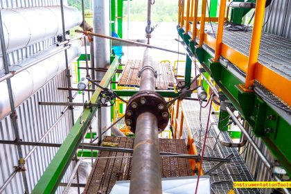
This is the Meter Regulating Station in Indonesia and is owned by Indonesia National Gas Company (PGN) or Perusahaan Gas Negara.
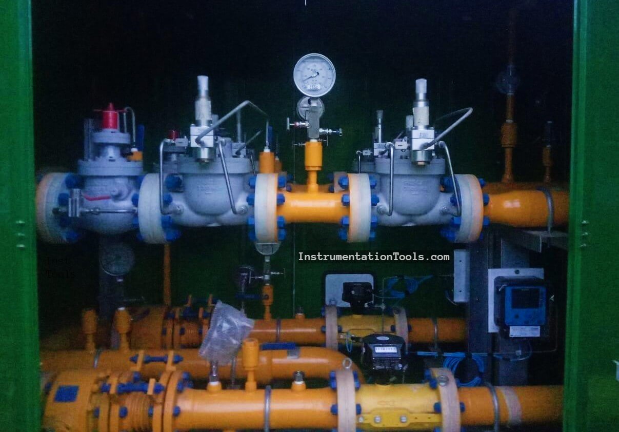
Before we discuss this plant in more detail, we must understand about the gas distribution system.
Gas Distribution System P&ID
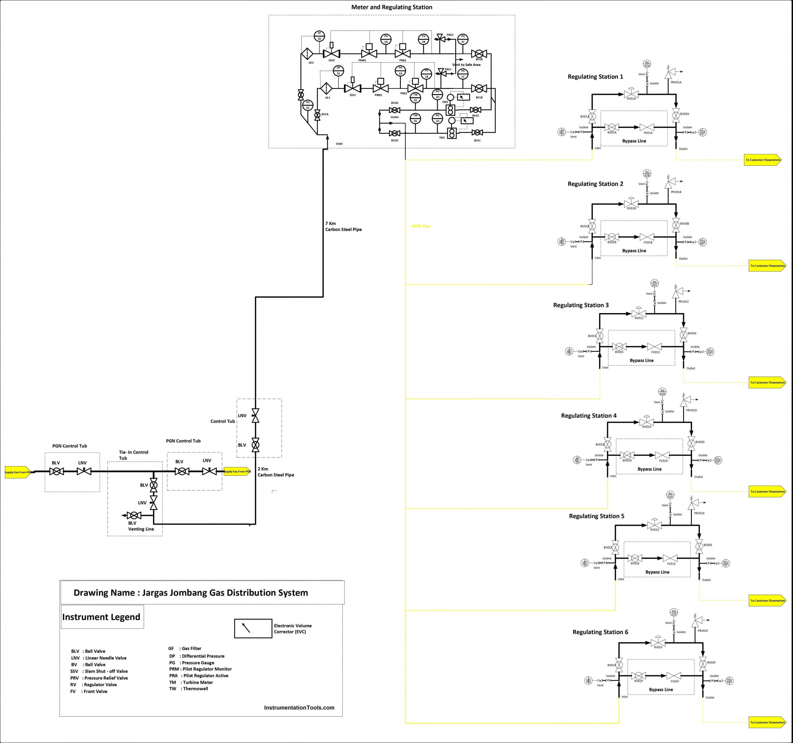
From the drawing, we know that the Meter Regulating Station (M/RS) is located after the tie-in line from the PGN line.
The gas is about 5 – 30 Barg from the tie-in line for the M/RS inlet. In this M/RS the gas is filtered, regulated, and measured until this outlet is 1 – 4 Barg.
So, what makes the gas is at pressure-reduced conditions? So, let’s check for the part of the P&ID at the M/RS section. And knowing the datasheet from these stations.
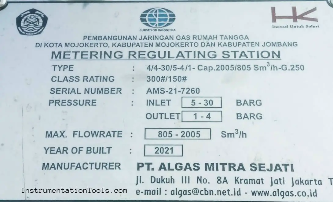
On the datasheet, we know the maximum flow rate, pressure, and G-Size from Turbine Meter (G-250).
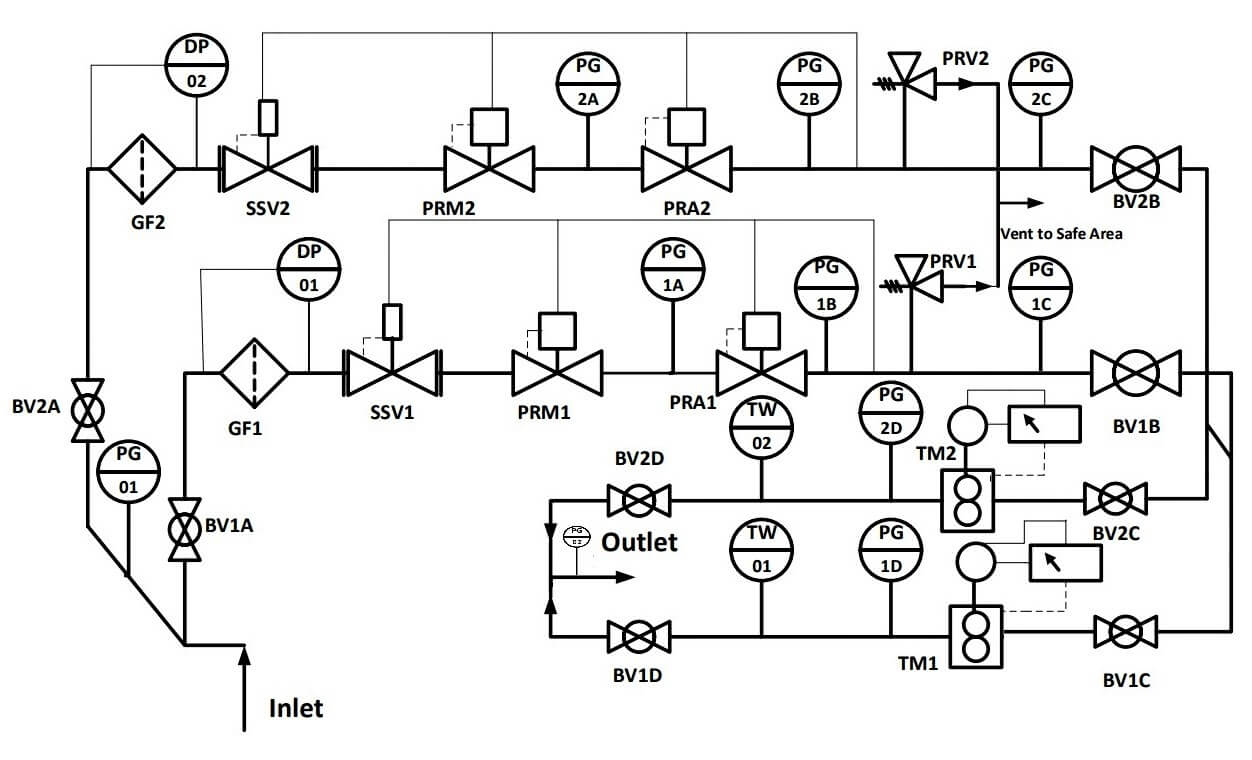
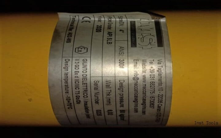
The first process is gas in from the inlet (insulation joint). There are 2 lines at upstream and downstream. We can know the pressure inlet from PG-01.
The gas is in via BV1/2A (Ball Valve). And after that, the gas passes the filter GF1/2 (Gas Filter) to filter the gas from impurities. And measured with the differential pressure gauge (DP).
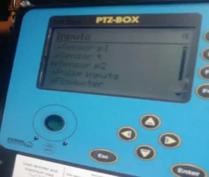
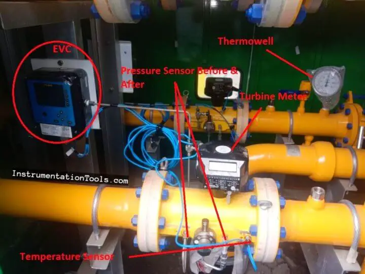
The gas is about 5 – 30 Barg. And after the DP gauge, the gas is regulated by SSOV (Slam-Shut Off Valve) to 4,5 Barg, Pilot Regulator Monitor (PRM) 4,1 Barg, and Pilot Regulator Active (PRA) 4 Barg and will go to the downstream section to be calculated with Electronic Volume Corrector (EVC) who’s connected with the pressure sensor, temperature sensor, a turbine meter with encoder to record the flowrate.
After that, the gas measured this temperature with thermowell too (TW1/2) and go to outlet insulation joint section and measured by PG 02 (The author forget to draw the outlet pressure gauge, so the draw on this P&ID is small than other instruments).
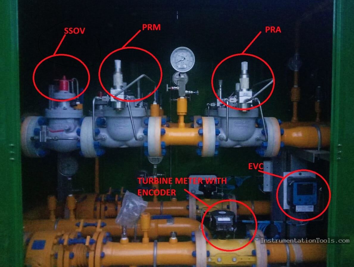
There are the PRV1/2 (Pressure Relief Valve) to relieve the pressure if there is overpressure at the upstream pressure.
It usually happened if the usage of the gas is suddenly decreased. The PRV is set on 4.3 Barg.
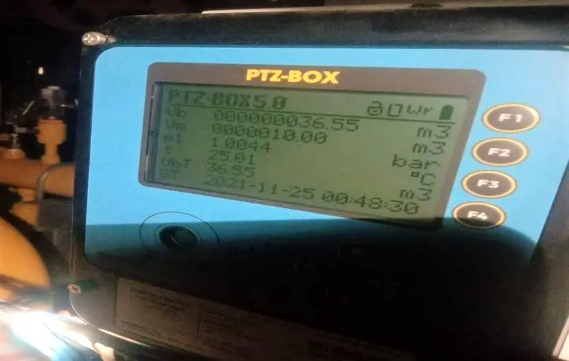
The picture above is showing about the parameters is measured by EVC. There are Vm (Volume at measurement conditions or nPsiG) and Vb (Volume at base conditions or 0Psig).
So the EVC is used to convert the gas flow rate from measured condition to base condition. In this case, gas compressibility law is available.
PV = nRT
If the gas temperature is low, so the pressure and the volume will be decreased than at higher temperature conditions.
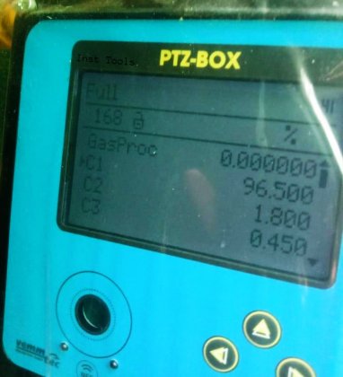
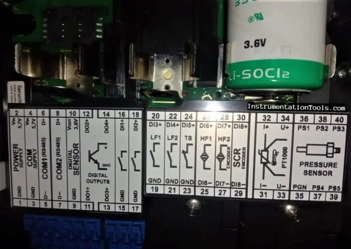
This equipment is equipped with a pressure sensor, temperature sensor (PT-100), and IGTM turbine meter G-250. It can be added by NAMUR sensor and Encoder. And we can monitor the gas composition such as C1, C2, C3, C4,….until H2.
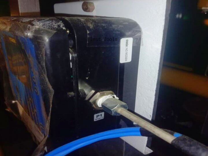
The equipment is featured by RS485 communication. So the gas value from EVC is can be collected and monitored with SCADA wireless (using GPRS) or not (using RS485).
To get good performance for the measure and regulating process at this gas distribution system, the equipment at the M/RS should be on good maintenance.
Author: Ramadhani Ichlasul Amal

Bachelor of Applied Instrumentation Engineering Sepuluh Nopember Institute of Technology (ITS). And now at Jargas Jombang Operational and Maintenance Team.





Terima kasih, sangat membantu ????